Electric Vehicle Steering Wheel Position Sensor

An electric vehicle, steering wheel technology, applied in the direction of converting sensor output, instruments, measuring devices, etc., can solve the problems of installation and calibration complexity, complex calculation formula, etc., to achieve high reliability, simple mechanical structure, strong anti-interference ability. Effect

Active Publication Date: 2021-07-27
JINING UNIV
View PDF13 Cites 0 Cited by
  • Summary
  • Abstract
  • Description
  • Claims
  • Application Information

AI Technical Summary

Problems solved by technology

This angular position sensor leads to a more complicated calculation formula for the angular position, and the structure of this angular position sensor leads to the complexity of installation and calibration

Method used


Image

  • Electric Vehicle Steering Wheel Position Sensor
  • Electric Vehicle Steering Wheel Position Sensor
  • Electric Vehicle Steering Wheel Position Sensor

Examples


Embodiment 1

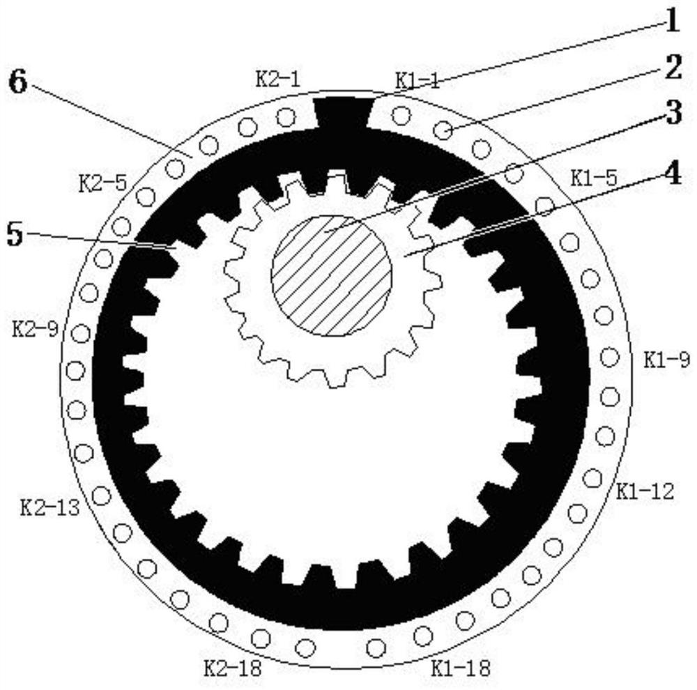
[0038] Such as Figure 1-6 As shown, the electric vehicle steering wheel position sensor of the present invention includes:

[0039] The external tooth pinion 4 is located at the innermost side of the position sensor body, the external tooth pinion 4 is set on the steering wheel shaft 3, and can rotate synchronously with the steering wheel shaft 3;

[0040] The large internal tooth gear 5 is located outside the external tooth pinion 4, and is meshed and rotationally connected with the external tooth pinion 4;

[0041] The number of teeth of the internal tooth bull gear 5 is three times that of the external tooth pinion gear 4;

[0042] The shading plate 1 is connected to the outer edge of the internal gear 5 and moves synchronously with the internal gear 5;

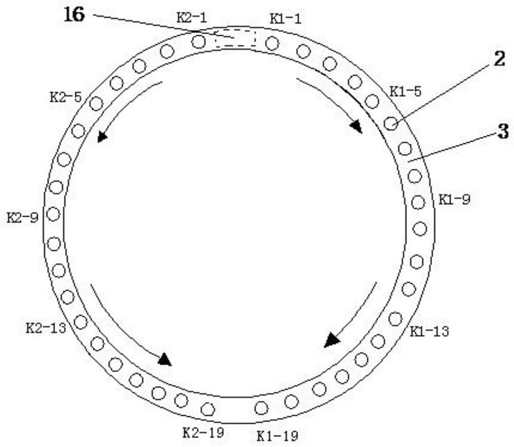
[0043] The position detection ring 6 is located on the outer side of the internal tooth gear 5, and a plurality of photoelectric gates 2 are placed symmetrically and evenly on the left half ring and the right half ring ...

Embodiment 2

[0066] Such as Figure 7 Shown is an application example of the electric vehicle steering wheel position sensor described in the present invention in implementing the electronic differential function on a two-wheel drive electric vehicle, including the electric vehicle steering wheel position sensor, and also includes a decoder, and the decoder is connected to the steering wheel position sensor , used to decode the detection signal output by the steering wheel position sensor, the output of the decoder is connected to the central controller on the electric vehicle, and the central controller is connected to the left motor and the right motor.

[0067] In order to further illustrate the above embodiment, the decoder includes a first decoder and a second decoder, which are respectively connected to the left half-ring output end and the right half-ring output end of the position detection loop 6 .

[0068] The working principle of the present embodiment is as follows: here, the t...


PUM


Abstract

The invention discloses a steering wheel position sensor for an electric vehicle, which belongs to the technical field of direction detection devices for electric vehicles, and comprises: an external tooth pinion located at the innermost side of the position sensor body, the external tooth pinion is set on the steering wheel shaft, and can be synchronized with the steering wheel shaft rotation; the internal gear is located outside the external pinion, and is meshed and rotated with the external pinion; the shading plate is connected to the outer edge of the internal gear and rotates with the internal gear; the position detection ring is located at On the outer side of the inner tooth gear, the left half ring and the right half ring on the position detection ring are symmetrically and evenly placed with multiple photoelectric gates, which are respectively used to detect the left-turn position and right-turn position of the steering wheel; the photoelectric gates can be blocked by the shading plate A corresponding detection signal is generated. It can provide steering wheel position information for the distributed drive electric vehicle power management system, has a simple structure and simple algorithm, and provides an effective supporting technical solution for the research and promotion of distributed drive electric vehicle technology.

Description

technical field [0001] The invention relates to a steering wheel position sensor for an electric vehicle, belonging to the technical field of direction detection devices for electric vehicles. Background technique [0002] The future development direction of electric vehicles is to install the electric motor directly on the driving wheel. This kind of electric vehicle is called distributed drive electric vehicle. Distributed drive electric vehicles need to collect steering wheel position information when turning, and implement electronic differential speeds on the inner and outer wheels through the "vehicle power distribution management system". The component used to detect the position information of the steering wheel is called a steering wheel position sensor, also known as a steering wheel angle position sensor. The existing steering wheel position sensors are divided into two types: contact type and non-contact type. Since the contact type angular position sensor has p...

Claims


Application Information

Patent Timeline
Patent Type & Authority Patents(China)
IPC IPC(8): G01D5/347B62D15/02
CPCB62D15/0215G01D5/3473
Inventor 常传忠
Owner JINING UNIV
Why Eureka
Try Eureka