Improved discharging device

A discharge device and an improved technology, applied in the direction of drying solid materials, grain processing, lighting and heating equipment, etc., to reduce the amount of operation, avoid moisture absorption, and increase continuity

Pending Publication Date: 2019-01-08
上海成界制药设备有限公司
View PDF20 Cites 2 Cited by
  • Summary
  • Abstract
  • Description
  • Claims
  • Application Information

AI Technical Summary

Problems solved by technology

[0003] The technical problem to be solved by the present invention is to provide an improved discharge device for the shortcomings existing in the drying process of the existing materials, aiming to solve the problem of realizing normal discharge without interrupting production, and achieving continuous and uninterrupted, increasing Continuity of production, reduced operation volume

Method used


Image

  • Improved discharging device
  • Improved discharging device
  • Improved discharging device

Examples


Embodiment 1

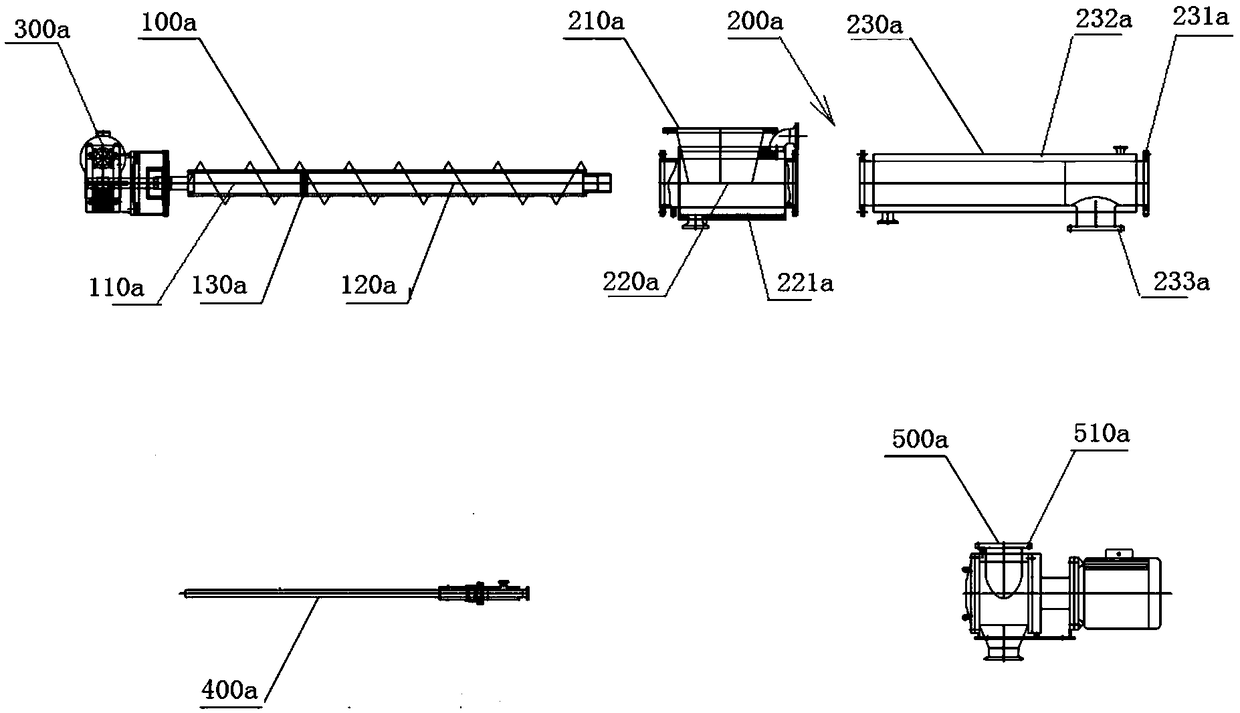
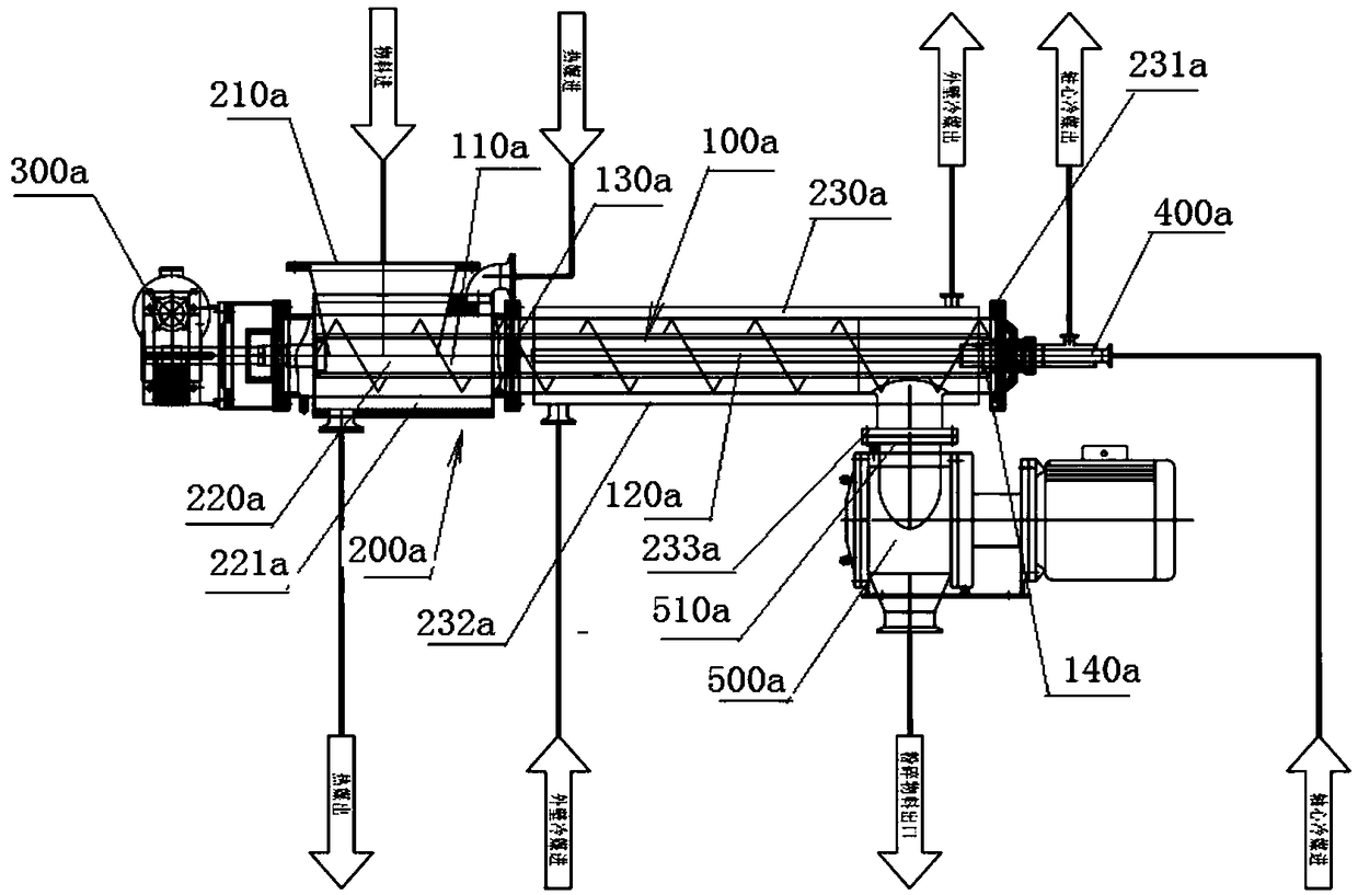
[0037] see figure 1 , figure 2 and image 3 The improved discharge device of this embodiment is an auger conveyor, which has an auger 100a, a feeding cylinder 200a set on the auger 100a, and a twisting auger installed at one end of the auger 200a. The auger driving mechanism 300a, the auger driving mechanism 300a is no different from the auger driving mechanism in the existing auger conveyor, and will not be described in detail here. The auger driving mechanism drives the auger to rotate for feeding. A feeding port 210a is provided at one end of the feeding barrel 200a close to the auger driving mechanism 300a, and the feeding port 210a communicates with the inside of the feeding barrel 200a.

[0038] The feeding tube 200a of this embodiment is divided into two sections, that is, a first section feeding tube 220a and a second section feeding tube 230a, and one end of the second section feeding tube 230a is away from the first section feeding tube 220a. The end of the auge...

Embodiment 2

[0052] see Figure 4 and Figure 5 , the improved discharge device of this embodiment is an auger conveyor, which has an auger 100 and a feeding tube 200 set on the auger 100 and an auger driving mechanism 300 installed at one end of the auger 200 , the auger driving mechanism 300 is no different from the auger driving mechanism in the existing auger conveyor, and will not be described in detail here. The auger driving mechanism 300 drives the auger 100 to rotate for feeding. An end of the feeding barrel 200 close to the auger driving mechanism 300 is provided with a feeding port 210 , and the feeding port 210 communicates with the inside of the feeding barrel 200 .

[0053] The feeding tube 200 of this embodiment is divided into two sections, that is, the first section feeding tube 220 and the second section feeding tube 230, and the second section feeding tube 231 is connected with the first section feeding tube 220 The end 221 far away from the auger driving mechanism 30...

Embodiment 3

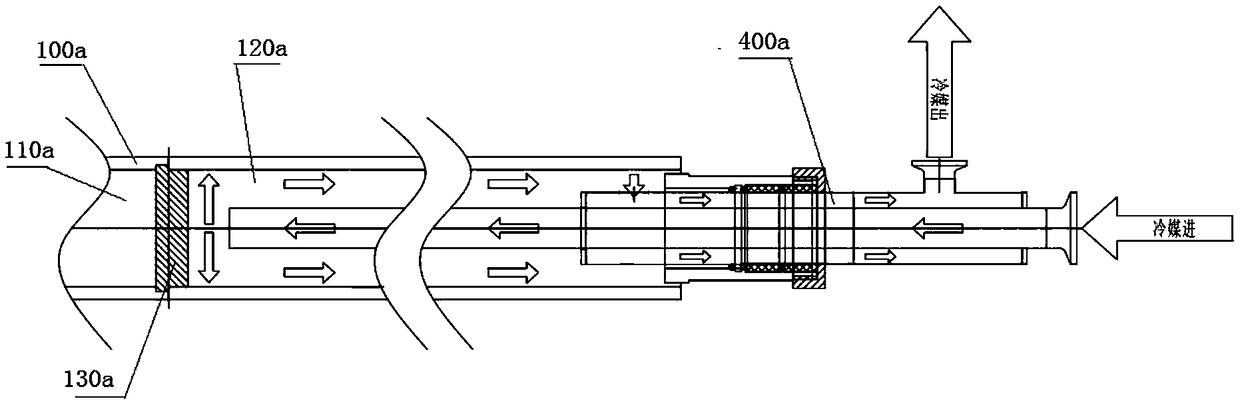
[0069] see Figure 6 and Figure 7 , the difference between the improved discharge device shown in the figure and the improved discharge device of embodiment 2 is that: the second section auger 120 is replaced by an auger fixing collar 150 with a through shaft 140, and the auger fixing collar 150 is fixed on one end of the through shaft 140, and the outer peripheral surface of the auger fixing collar 150 is level with the outer peripheral surface of the auger 100. The end of the dragon shaft 130 away from the auger driving mechanism 300 can be rotatably connected, and the through shaft 140 can be made into a water jacket, and the inner hole thereof is led into a refrigerant. The hot dry material in the equipment is relatively soft and has good plasticity. After the material enters the second discharge section, due to the existence of the through shaft 140, the material is plasticized into a state similar to a hollow cylinder, which increases the cooling efficiency and facilit...


PUM


Abstract

The invention discloses an improved discharging device which comprises a first discharging section and a second discharging section, wherein materials are delivered from the first discharging sectionto the second discharging section; and a temperature of the materials at the second discharging section is obviously lower than that of the materials at the first discharging section. In equipment provided by the invention, the hot dry materials are relatively soft and have excellent plasticity; the materials enter a cooling section, become hard and brittle after being cooled, and are convenientlycrushed in a latter stage; the materials are crushed into fine powder after entering a crusher through the improved discharging device provided by the invention; and the crushed materials are discharged downward. The improved discharging device provided by the invention can discharge the materials normally without interrupting production, achieves continuous and uninterrupted discharging, improves production continuity, reduces operating quantity, and is linked to the crusher to directly discharge the fine powder as products, avoid a moisture absorption phenomenon during re-grinding and ensure quality and uniformity of shape of the products.

Description

technical field [0001] The invention relates to the technical fields of pharmacy, food and chemical equipment, in particular to an improved discharge device suitable for discharging important extracted and dried products. Background technique [0002] In the vacuum drying process of pharmaceutical production at the present stage, hot materials are still very soft and easy to accumulate and stick into agglomerates. Once cooled, they will harden and agglomerate. It is difficult to crush large agglomerates in the later stage. The process of crushing is also easy to absorb moisture, which affects the quality of materials. In addition, because the drying process is carried out under vacuum, it is necessary to temporarily stop the machine when using the general discharge method, and then the vacuum can be broken before the material can be taken out. The operation of the whole process is more loaded down with trivial details, and the continuity is not strong. Contents of the inv...

Claims


Application Information

Patent Timeline
Patent Type & Authority Applications(China)
IPC IPC(8): B02C23/02F26B25/00
CPCF26B25/002B02C23/02
Inventor 方志张维豪陆煜
Owner 上海成界制药设备有限公司
Why Eureka
Try Eureka