Intelligent meter-valve integrated water meter

A smart meter and integrated technology, applied in liquid/fluid solid measurement, satellite radio beacon positioning system, measuring device, etc., can solve the problems of water worry and real-time viewing, and achieve easy replacement, small size, and improved The effect of tightness

Active Publication Date: 2019-01-08
BEIJING HUIYI SCI & TECH
View PDF14 Cites 0 Cited by
  • Summary
  • Abstract
  • Description
  • Claims
  • Application Information

AI Technical Summary

Problems solved by technology

[0004] The purpose of the present invention is to provide a smart meter valve integrated water meter. By isolating the control chamber and the valve chamber in the same housing, the entire water meter has a simple and compact structure, a small volume, and is easy to use. Th

Method used


Image

  • Intelligent meter-valve integrated water meter
  • Intelligent meter-valve integrated water meter
  • Intelligent meter-valve integrated water meter

Examples


Embodiment 1

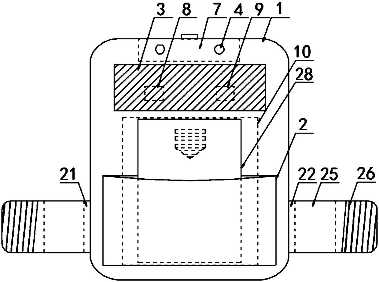
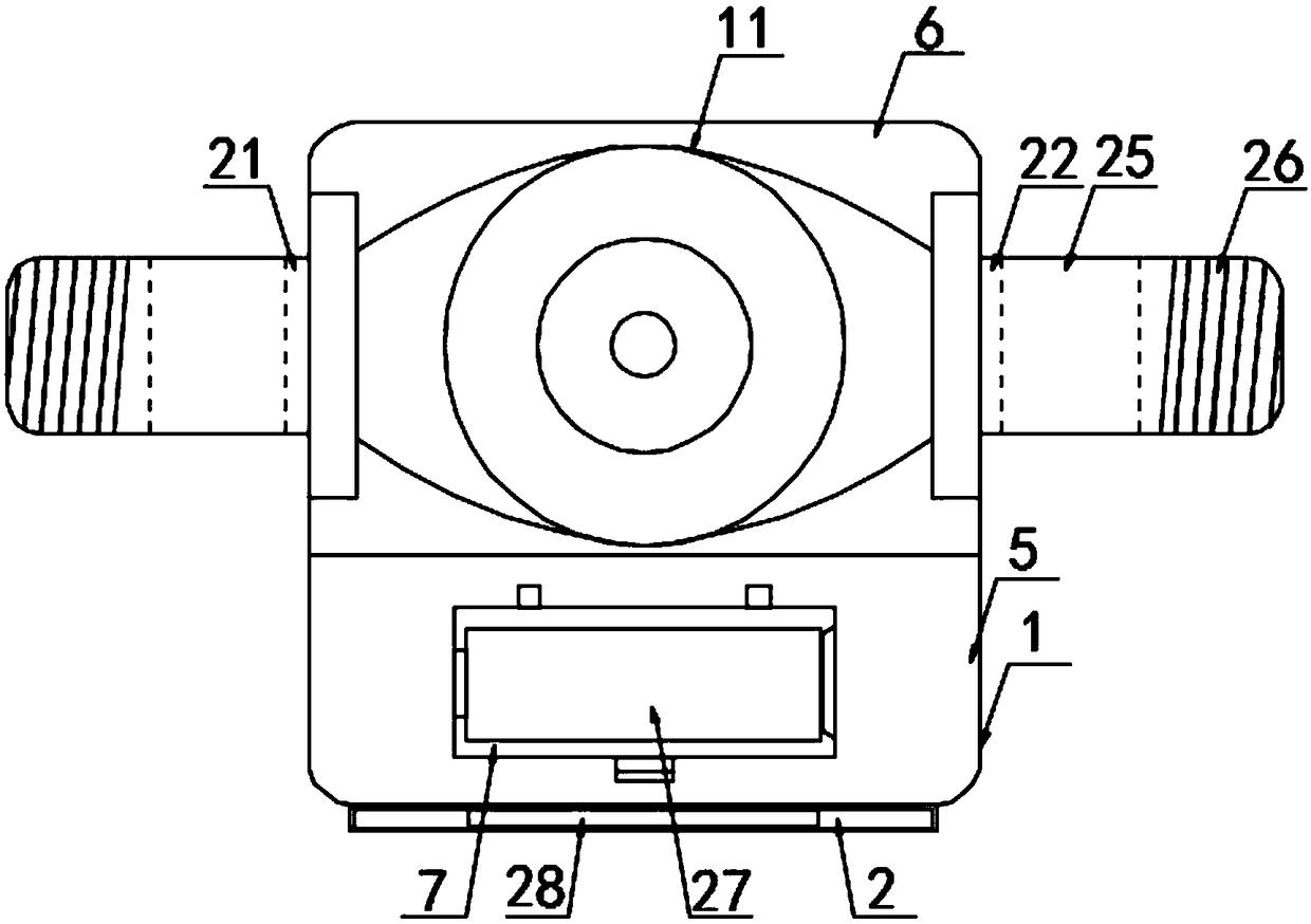
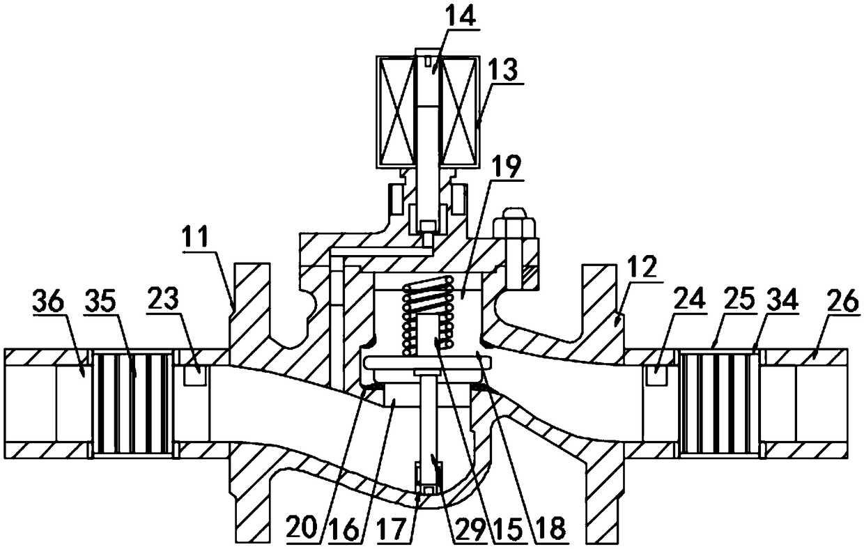
[0030] according to Figure 1-3 The shown water meter with integrated meter and valve includes a housing 1, a card slot 2 is provided on the front side of the housing 1, a display 3 is provided on the top of the card slot 2, and an indicator light 4 is provided on the top of the display 3 , the inside of the housing 1 is provided with a control chamber 5 and a valve chamber 6, the inside of the control chamber 5 is provided with a battery slot 7, a single-chip microcomputer 8, a GPS locator 9 and an IC card reader 10, and the inside of the valve chamber 6 A solenoid valve 11 is provided, and the solenoid valve 11 includes a valve body 12, a coil 13, a magnetic core 14, a valve stem 15, a piston 16 and a limit detection mechanism 17, and the inside of the valve body 12 is provided with a piston movable cavity 18, so The top of the piston movable chamber 18 is provided with a valve stem movable chamber 19, the inner wall of the valve body 12 corresponding to the top and bottom o...

Embodiment 2

[0033] according to figure 2 In the shown water meter with integrated meter and valve, the housing 1 is set as a square body, the corners of the housing 1 are set as rounded corners, the valve cavity 6 is set on the rear side of the control cavity 5, and the control cavity 5 and the valve chamber 6 are provided with a partition to prevent the internal structure of the control chamber 5 from being affected by water leakage in the valve chamber 6. The battery tank 7 is arranged on the top of the control chamber 5, and the inside of the battery tank 7 is provided with a storage battery 27. The top of the battery tank 7 is provided with a cover plate, the cover plate is movably clamped with the battery tank 7, the single-chip microcomputer 8 is arranged at the bottom of the battery tank 7, the GPS locator 9 is arranged on one side of the single-chip microcomputer 8, and the IC card The card reader 10 is arranged on the bottom of the GPS locator 9 and corresponds to the card slot ...


PUM


Abstract

The invention discloses an intelligent meter-valve integrated water meter, comprising a shell, wherein a neck is formed in the front side of the shell, a display is arranged at the top of the neck, anindicator lamp is arranged at the top of the display, a control cavity and a valve cavity are formed in the shell, a battery jar, a single chip microcomputer, a GPS positioner and an IC card reader are arranged in the control cavity, a solenoid valve is arranged in the valve cavity, the solenoid valve comprises a valve body, a coil, a magnetic core, a valve rod, a piston and a limiting detectionmechanism, a piston moving cavity is formed in the valve body, a valve rod moving cavity is formed in the top of the piston moving cavity, and sealing pads are arranged on valve body inner walls corresponding to the top and the bottom of the piston moving cavity. According to the intelligent meter-valve integrated water meter disclosed by the invention, the control cavity and the valve cavity areseparately designed in the same shell, the entire water meter structure is simple and compact, the volume is relatively small, and by integrating the valve, the water meter and a filtering mechanism,the water condition can be viewed in real time, so that the water consumption is at ease, and no triple installation of the valve, the water meter and the filter is required.

Description

technical field [0001] The invention relates to the field of a smart meter-valve integrated water meter, in particular to a smart meter-valve integrated water meter. Background technique [0002] At present, most IC card water meters adopt the split connection structure of the water meter body and the circuit control valve. As long as the water meter base meter is installed with a mechanical counter, the signaling device is connected with a separately manufactured valve by threaded connection, and the battery is installed in the plastic The interior of the shell and the information reading method mainly constitute the IC card water meter, but the existing IC card water meter has the problems of single function, complex structure, large volume and inconvenient installation. [0003] Therefore, it is necessary to invent a kind of smart water meter integrated with meter and valve to solve the above problems. Contents of the invention [0004] The purpose of the present inven...

Claims


Application Information

Patent Timeline
IPC IPC(8): G01F15/00G01S19/14
CPCG01F15/005G01S19/14
Inventor 鲍颖慧鲍学华王德慧张孟叶卫民
Owner BEIJING HUIYI SCI & TECH
Why Eureka
Try Eureka