
A three-phase step-down PFC rectifier circuit

A rectifier circuit and step-down technology, which is applied in the field of three-phase step-down PFC rectifier circuit, can solve the problems of complex drive and control strategies, high filter current requirements, large output current ripple, etc., and achieve drive and control strategies Simple, wide range of use, simple current control effect

Pending Publication Date: 2019-01-08
NANCHANG HANGKONG UNIVERSITY
View PDF0 Cites 0 Cited by
  • Summary
  • Abstract
  • Description
  • Claims
  • Application Information

AI Technical Summary

Problems solved by technology

Three-phase single-switch Boost PFC circuit, in order to achieve decoupling between the three phases, three inductors are placed on the AC side, and work in the current discontinuous mode, which is characterized by simple current control, but the input and output of the circuit The current ripple is large, the filter current is high, and the output voltage is too high, which brings certain difficulties to the selection of the power tube. This circuit is generally used in occasions where the output power is less than 10kw and the current THD is not strict; Although the three-phase multi-switch can control the input current with high precision and obtain excellent performance, the driving and control strategies are complex and the cost is high, which is suitable for high-power applications.

Method used


Image

  • A three-phase step-down PFC rectifier circuit
  • A three-phase step-down PFC rectifier circuit
  • A three-phase step-down PFC rectifier circuit

Examples


Embodiment Construction

[0025] A specific embodiment of the present invention will now be described in detail in conjunction with the accompanying drawings.

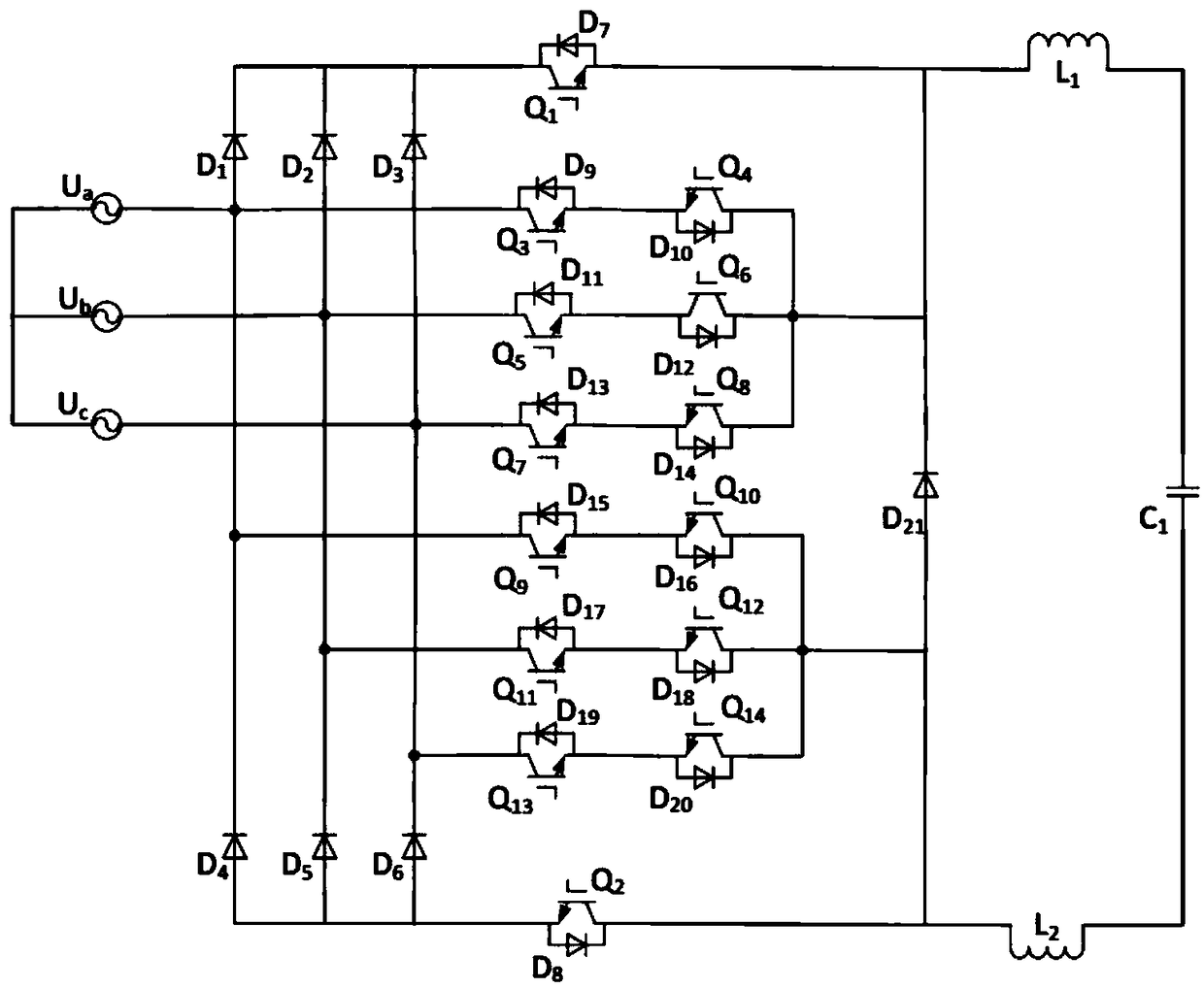
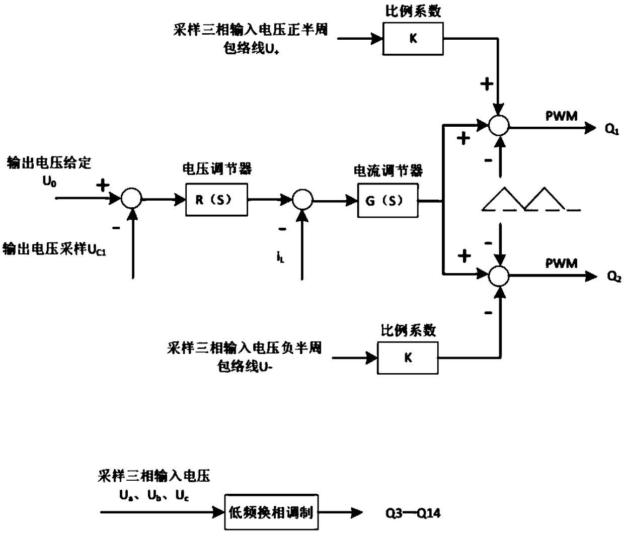
[0026] Such as figure 1 with figure 2 As shown, a three-phase step-down PFC rectifier circuit includes: a three-phase voltage source circuit, a three-phase uncontrolled rectifier circuit, two symmetrical buck circuits and an active third harmonic current injection circuit.

[0027] The three-phase voltage source is composed of three sinusoidal voltage sources a, b, and c which are 120° to each other. One end of the a, b, and c three-phase voltage sources is connected together, and the other end is respectively connected to the three-phase uncontrolled rectification circuit.

[0028] Three-phase uncontrolled rectification circuit, including diode D 1 、D 2 、D 3 、D 4 、D 5 、D 6 ,D 1 anode with D 4 The cathodes are connected to form the first series circuit, D 2 anode and D 5 The cathodes are connected to form a second series circuit, D ...


PUM


Abstract

A three-phase step-down PFC rectifier circuit comprises a three-phase voltage source, a three-phase uncontrolled rectifier circuit, two symmetrical buck circuits and an active third harmonic current injection circuit. Compared with the three-phase LC filter passive power factor correction circuit, the power factor can reach 1.0, and the output voltage is controllable. Compared with the three-phaseboost-buck-type PFC rectifying circuit, the invention can output lower voltage without boosting circuit. As compare with that three-phase single-switch correction circuit, the current control is simple, the inductor current operates in the continuous mode, the input and output current ripple is small, and only two inductor are required, the three-phase decoupling is not required, and the controlis simple; Compared with the three-phase multi-switch power factor correction circuit, the driving and control strategy of the invention is simple, the cost is greatly saved, the realization is convenient, and the use range is wide.

Description

technical field [0001] The invention relates to the technical field of power factor correction, in particular to a three-phase step-down PFC rectifier circuit. Background technique [0002] Power Factor Correction Technique (Power Factor Correction Technique) is a basic technology in the field of power electronics and industry. It is used to suppress harmonic pollution to reduce the harm caused by high-order current harmonics to the power grid and various electrical equipment. With the increase of electrical equipment, higher requirements for high efficiency, high power density and high power factor are also put forward for power converters. Therefore, various new PFC conversion topologies have emerged as the times require. At present, there are many studies on single-phase power factor correction technology, which are quite mature in terms of circuit topology and control, while the research on three-phase power factor correction is relatively late. In recent years, with th...

Claims


Application Information

Patent Timeline
Patent Type & Authority Applications(China)
IPC IPC(8): H02M1/42
CPCH02M1/4216H02M1/4291Y02B70/10
Inventor 刘斌陈柏宇江弋横刘海涛蔡金琪
Owner NANCHANG HANGKONG UNIVERSITY
Learn More