Foot-ankle fusion structure and joint fusion device

An ankle and locking hole technology, applied in the field of medical devices, can solve problems such as poor stability of fusion nails and large wound size, and achieve the effect of enhanced connection stability, small surgical incision, and convenient and quick surgery

Inactive Publication Date: 2019-01-11
大泗医疗生物科技有限公司
View PDF10 Cites 1 Cited by
  • Summary
  • Abstract
  • Description
  • Claims
  • Application Information

AI Technical Summary

Problems solved by technology

[0005] The purpose of the present invention is to provide an ankle fusion structure to solve the technical problems in the prior art that the stability of the fusion nail is poor and the required wound size is large

Method used


Image

  • Foot-ankle fusion structure and joint fusion device
  • Foot-ankle fusion structure and joint fusion device
  • Foot-ankle fusion structure and joint fusion device

Examples


Embodiment 1

[0039] like Figure 1-Figure 10 As shown, the ankle fusion structure provided by the embodiments of the present invention includes:

[0040] Main nail 10 and locking screw 20, wherein:

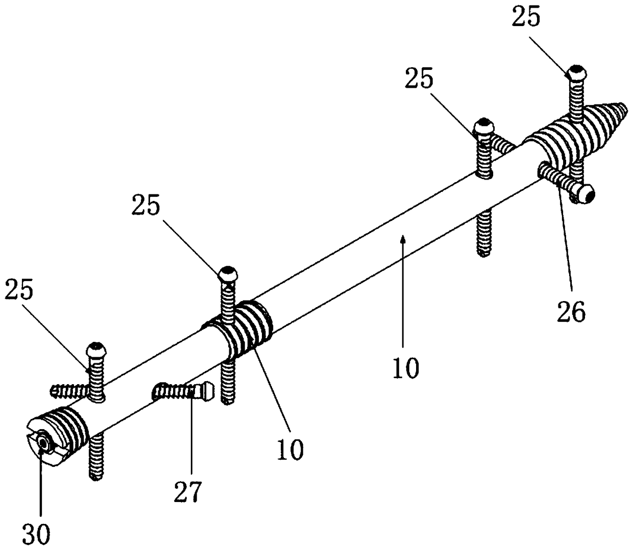
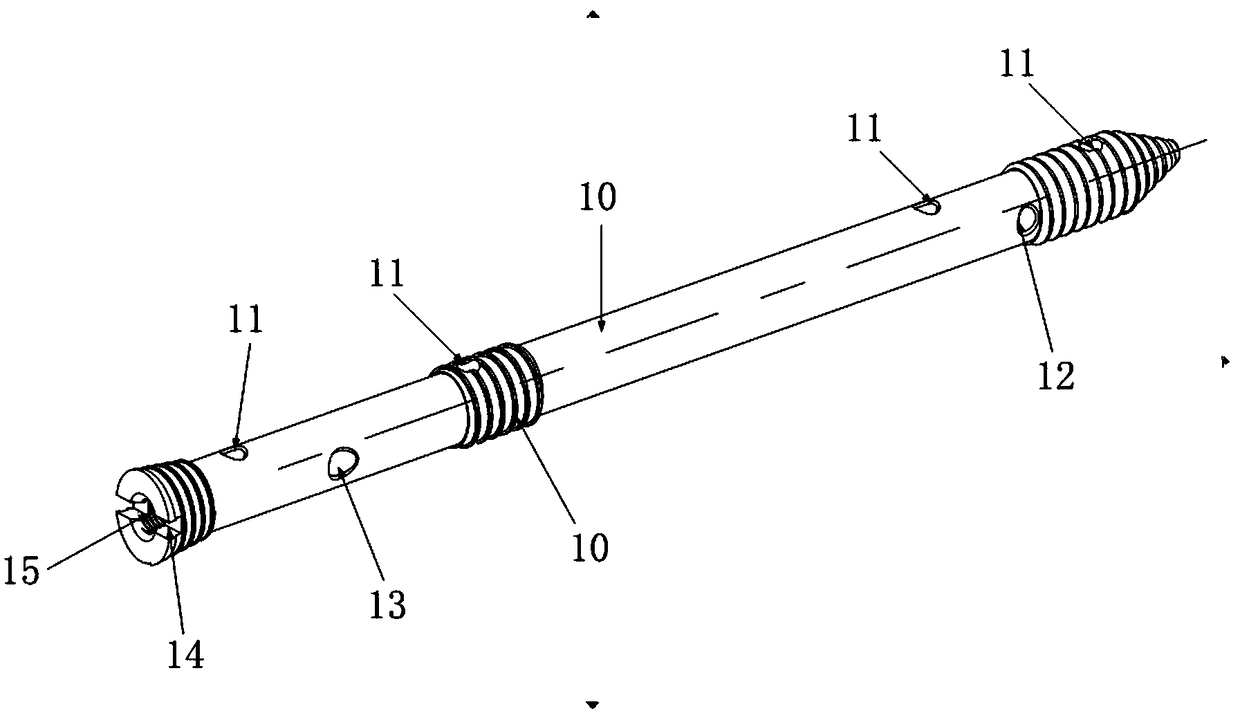
[0041] The main nail 10 is provided with multiple sets of locking holes, the axes of the locking holes in each set of locking holes extend in different directions, and the locking screw 20 can pass through any locking hole in any set of locking holes.

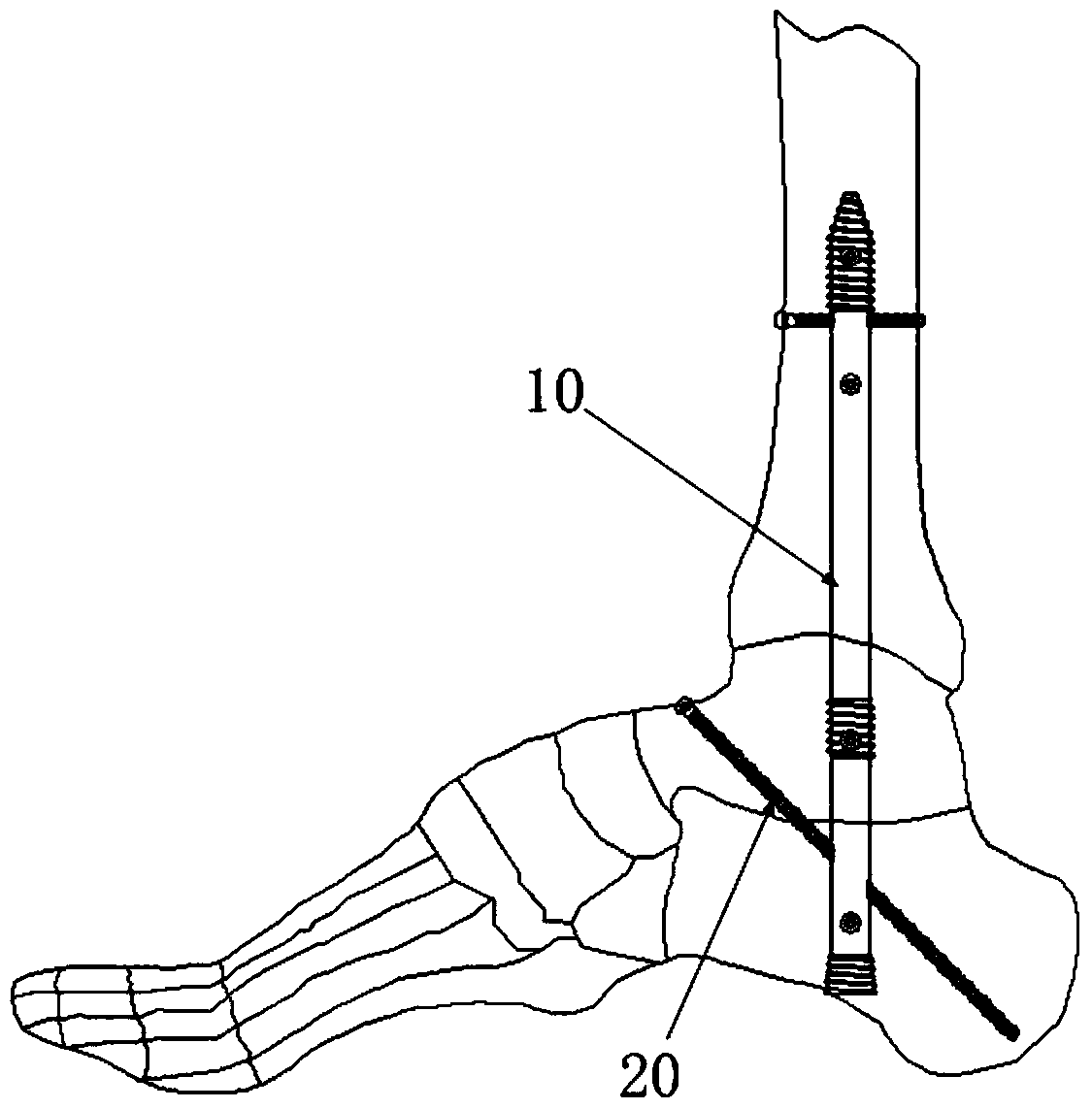
[0042] like figure 1 As shown, the main nail 10 extends into the inside of the ankle, and a plurality of locking screws 20 are inserted on the main nail 10, and the plurality of locking screws 20 are installed in locking holes at different positions of the main nail 10 respectively. figure 1 Within the visible range, at least one locking screw 20 is arranged obliquely relative to the main nail 10 , at least one screw is arranged horizontally along the left and right directions, and at least four screws are arranged along the vertical directio...

Embodiment 2

[0058] Embodiment 2 of the present invention provides a joint fusion device, including the ankle fusion structure provided in Embodiment 1 above.

[0059] The ankle-foot fusion structure can be applied to the osteotomy internal fixation of the ankle joint, ankle arthrodesis and tibial-talar fusion. The ankle joint is located at the distal tibia, including the talus and calcaneus. The three calcaneus are axially integrated, and the fusion structure of the ankle is implanted into the distal tibia at an angle at the middle joint between the calcaneus and the talus for fixation.

[0060] Further, the joint fusion device may also include a support frame matched with the ankle fusion structure, and after the main nail is drilled into the ankle joint, the main nail is fixed by the support frame, so as to facilitate the installation of the locking screw. The support frame is provided with a threaded hole, and the thread at the proximal end of the main nail matches the threaded hole on...


PUM


Abstract

The invention provides a foot-ankle fusion structure and a joint fusion device, which relate to the technical field of medical instruments and solve the problem that the stability of the fusion nail in the prior art is poor and the required wound size is large. The ankle-foot fusion structure comprises a main screw and a locking screw, a plurality of sets of locking holes are arranged on the mainscrew, the axial extension directions of the locking holes in each set of locking holes are different, and the locking screw can pass through any one of the locking holes in any set of locking holes.The foot-ankle fusion structure is applied to the foot-ankle fusion operation; the main screw and the locking screw mutually cooperate with each other, the stability is strong, the locking screw is fixed on the main screw, the position of the locking screw is easy to locate, and the wound size is small.

Description

technical field [0001] The invention relates to the technical field of medical devices, in particular to an ankle fusion structure and a joint fusion device. Background technique [0002] Ankle fusion nails are usually used in the treatment of femoral neck fractures to fix the injured part through surgical techniques to facilitate recovery of the injured part. [0003] Ankle fusion is a kind of osteosynthesis, and it is also a new development trend of modern fracture fixation. It adopts fracture pressure reduction technology, and uses intramedullary implant central axis fixation to maintain fracture alignment, so that surgical exposure and Soft tissue stripping is minimized, which improves fracture healing rates. [0004] However, in the current process of ankle fusion surgery, multiple heel fusion nails are implanted into the patient's ankle according to the patient's injury site, and the stability of the fusion nail in the ankle is poor; in addition, due to the difficulty...

Claims


Application Information

Patent Timeline
IPC IPC(8): A61B17/68A61B17/86
CPCA61B17/683A61B17/685A61B17/8605A61B17/8635A61B17/8685A61B2017/564
Inventor 吴得宏
Owner 大泗医疗生物科技有限公司
Why Eureka
Try Eureka