
Countable drainage bag

A drainage bag and drainage tube technology, applied in the field of blood volume detection equipment, can solve the problem of inconvenient storage of trays or auxiliary parts, and achieve the effects of facilitating blood dumping and improving sealing effect

Pending Publication Date: 2019-01-11
THE SECOND AFFILIATED HOSPITAL OF NANJING MEDICAL UNIV
View PDF0 Cites 1 Cited by
  • Summary
  • Abstract
  • Description
  • Claims
  • Application Information

AI Technical Summary

Problems solved by technology

[0004] The purpose of the present invention is to provide a countable drainage bag to solve the problem that the existing trays or auxiliary parts are not convenient for storage in the above-mentioned background technology

Method used


Image

  • Countable drainage bag
  • Countable drainage bag
  • Countable drainage bag

Examples


Embodiment 1

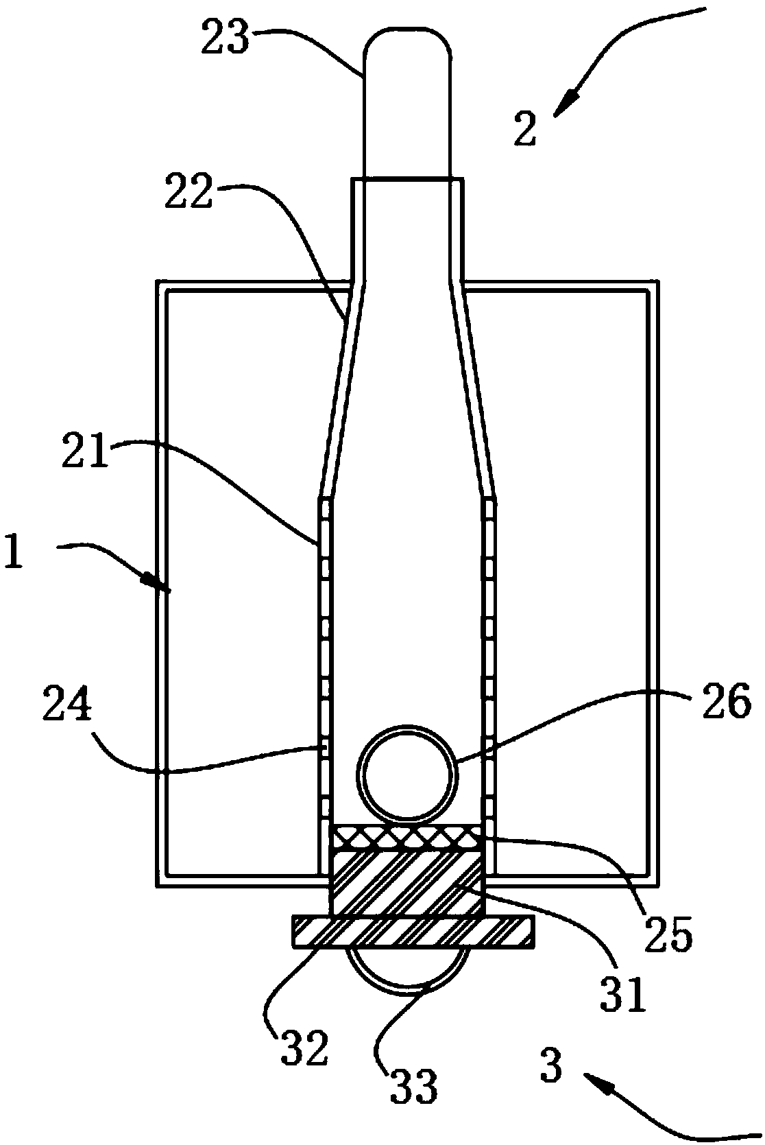
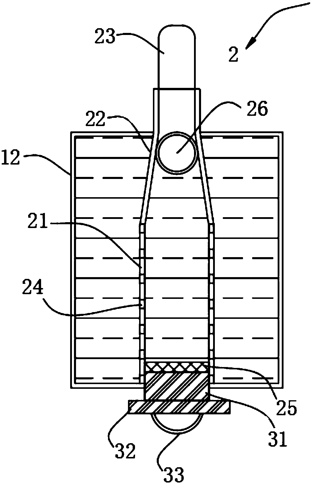
[0024] A countable drainage bag such as figure 1 and 3 As shown, a blood drainage bag 1 is included, and the blood drainage bag 1 includes a bag body 11. A blood count scale area 12 is arranged on the outer surface of the bag body 11. A drainage structure 2 is arranged at the center of the bag body 11. The drainage structure 2 includes a drainage structure. Tube 21, the top of the drainage tube 21 is connected to the flow-limiting tube 22, the diameter of the flow-limiting tube 22 from top to bottom becomes larger, and the end of the flow-limiting tube 22 away from the drainage tube 21 passes through the top surface of the bag body 11 and extends To the outside of the bag body 11, the end of the flow-limiting tube 22 away from the drainage tube 21 is connected with a blood-drawing connection tube 23, and the outer wall of the drainage tube 21 is provided with a number of through holes 24 arranged evenly and equidistantly. The drainage tube 21 is far away from the flow-limiting...

Embodiment 2

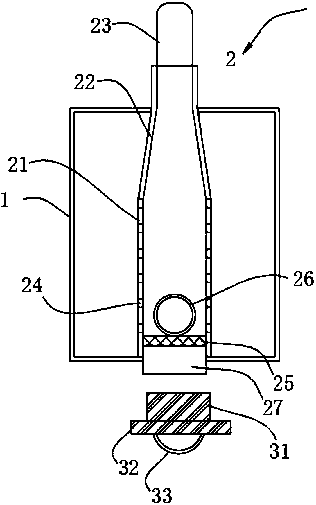
[0033] In order to solve the problem of inconvenient pouring in Example 1, the inventor made improvements to the sealable tube 27 of Example 1, as a preferred technical solution of Example 1, such as image 3 As shown, one end of the sealable tube 27 away from the drainage tube 21 is provided with a detachable sealing structure 3, the detachable sealing structure 3 includes a sealing plug 31, and one end of the sealing plug 31 is connected with a sealing cap 32, and the sealing cap 32 is far away from the sealing plug One side middle part of 31 is provided with pull ring 33.

[0034] Further, the size of the sealing plug 31 is adapted to the size of the sealable tube 27, and the outer wall of the sealing plug 31 is a threaded structure, the inner wall of the sealable tube 27 is a threaded structure, and the sealing plug 31 is threadedly connected with the sealable tube 27 .

[0035] In this embodiment, the sealable tube 27 can be sealed by the provided sealing plug 31, and th...


PUM


Abstract

The invention relates to the technical field of blood volume measuring equipment, in particular a countable drainage bag, comprising a blood drainage bag, wherein the blood drainage bag includes a bagbody, a blood counting calibration area is arranged on the outer surface of the bag body, a drainage structure is arranged at the center of the bag body, a drainage structure includes a drainage tube, the top of the drainage tube is connected with a finite flow tube, the diameter of the current limiting tube from top to bottom increases from small to large, an end portion of the flow restrictiontube remote from the drainage tube passes through the top surface of the bag body and extends to the outside of the bag body, one end part of the flow restriction tube away from the flow restriction tube is connected with a blood drawing connecting tube, the outer wall of the flow restriction tube is provided with uniformly equidistant arranged through holes, one end part of the flow restriction tube away from the flow restriction tube is connected with a sealable tube, a mesh cover is installed at the bottom of the flow restriction tube, and a floating ball is placed inside the flow restriction tube. The invention can read out the blood volume in the bag through the blood counting calibration area arranged on the bag body, and the recording panel can assist the medical personnel to recordthe blood volume.

Description

technical field [0001] The invention relates to the technical field of blood volume detection equipment, in particular to a countable drainage bag. Background technique [0002] In clinical surgery, when subcutaneous infection or effusion occurs in the incision, the conventional treatment method is to open the incision, expand the wound surface and change the dressing. Once the wound is open, it takes a very long time to change the dressing. Generally, it takes about one month for the wound granulation tissue to be fresh and suitable for re-suturing. After re-suturing, the wound tension is high and the scar is large after healing. Therefore, wound drainage tubes are widely used. Drainage and cleaning of subcutaneous infected blood in the incision. [0003] Nowadays, after the infected blood is discharged through the wound drainage tube, it is necessary to collect and record the discharge of the discharged blood, connect the blood volume drainage bag to one end of the draina...

Claims


Application Information

Patent Timeline
Patent Type & Authority Applications(China)
IPC IPC(8): A61M1/00G01F22/00
CPCG01F22/00A61M1/69A61M1/84
Inventor 曹欣
Owner THE SECOND AFFILIATED HOSPITAL OF NANJING MEDICAL UNIV
Learn More