Pelvic floor repair rod
A technology of locking section and transition section, applied in the field of pelvic floor repair rods, can solve the problems of complex structure of pelvic floor repair rods, fixed size of repair head, etc., so as to improve pelvic floor tension, increase muscle circumference and lock effect Good results
- Summary
- Abstract
- Description
- Claims
- Application Information
AI Technical Summary
Problems solved by technology
Method used
Image
Examples
Embodiment 1
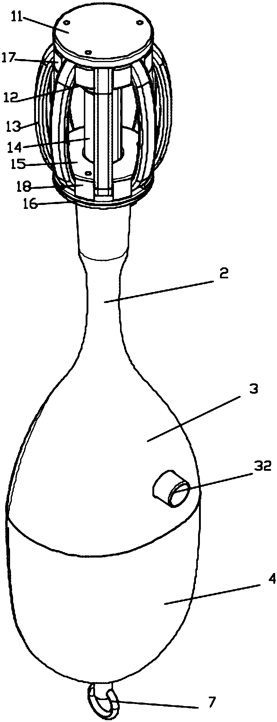
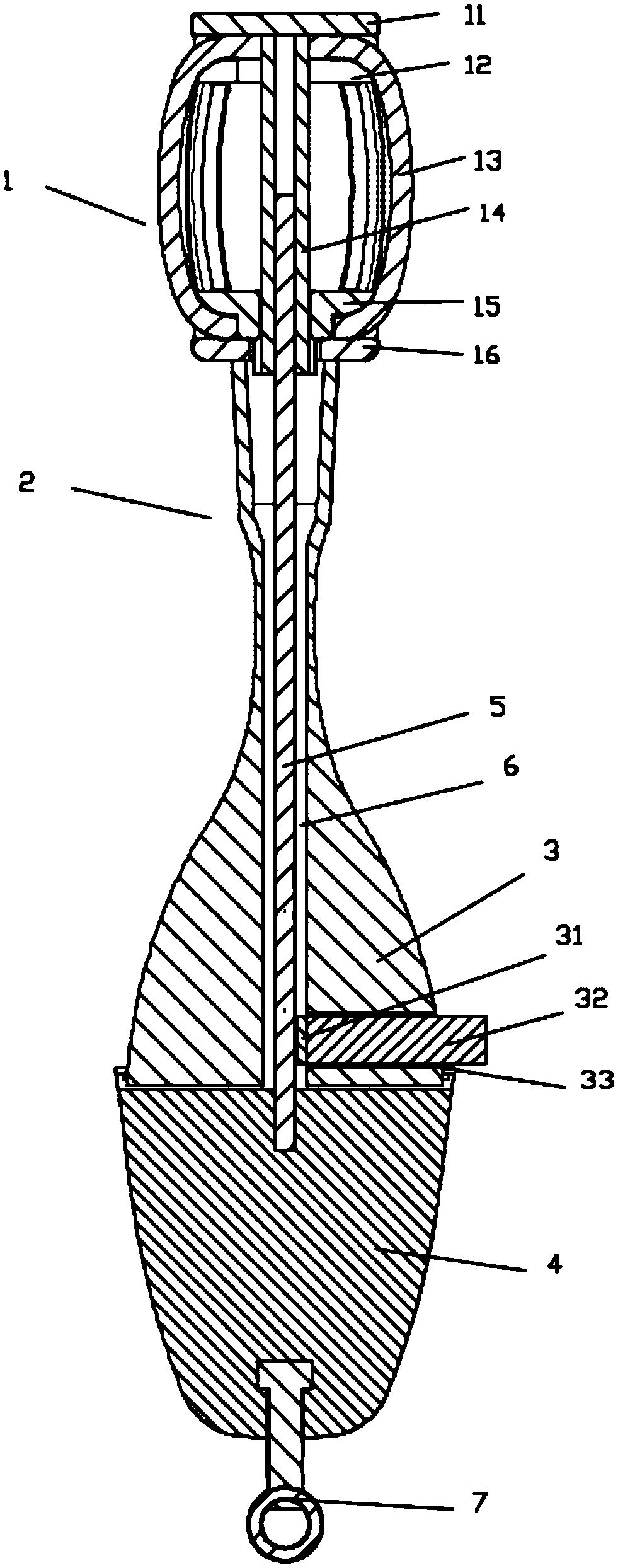
[0032] Such as figure 1 As shown, this embodiment provides a pelvic floor repair rod, including a repair head 1 and a repair handle, the repair head 1 is a retractable drum-shaped repair head 1, and the interior of the repair head 1 is provided with a device to control the expansion and contraction of the repair head 1. The lifting mechanism, the repair handle includes a transition section 2 and a hand-held section, the transition section 2 and the hand-held section are both hollow structures, the hand-held section includes a relatively rotatable locking section 3 and a rotating section 4, the repair head 1, the transition section 2 It is fixedly connected with the locking section 3 in turn, and the lower part of the lifting mechanism is sequentially moved inside the transition section 2 and the locking section 3. The bottom of the lifting mechanism is fixedly connected with the rotating section 4, and the locking section 3 is provided with a lock for locking the lifting mechan...
Embodiment 2
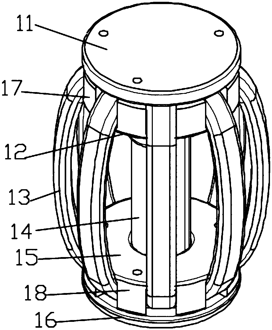
[0038] Such as figure 2 and image 3 As shown, this embodiment is further optimized on the basis of Embodiment 1, specifically, the repair head 1 includes a threaded sleeve 14 with threads inside, and eight elastic support bars 13 are arranged outside the threaded sleeve 14, and the threaded sleeve The upper part of the cylinder 14 is fixedly provided with an upper baffle 11 and an upper bracket 12 from top to bottom, and the lower part of the threaded sleeve 14 is provided with a lower baffle 16 and a lower bracket 15 which are fixedly connected to each other successively from bottom to top. 16 is fixedly connected with the top of the transition section 2, the top of the upper support 12 is provided with an upper protrusion 17, the bottom of the lower support 15 is provided with a lower protrusion 18, and the upper part of the elastic support bar 13 is fixed on the upper baffle plate 11, the upper support 12 and the upper protrusion In the groove formed by 17, the lower par...
Embodiment 3
[0042] Such as Figure 1 to Figure 3 As shown, this embodiment is further optimized on the basis of Embodiment 2. Specifically, the end of the locking bolt 32 close to the lifting bolt 5 is fixed with a rubber layer 31, and the rubber layer 31 is set to increase the connection between the end of the locking bolt 32 and the lifting bolt. 5 between the friction, prevent slipping, very high locking effect.
[0043] As a preferred method, the diameter of the transition section 2 is smaller than the diameter of the locking section 3, and the joints of the lower baffle plate 16, the transition section 2 and the locking section 3 are arc transitions, and the diameter of the transition section 2 is set to be smaller than that of the locking section. The diameter of 3 makes it easy to move along the transition section 2 after the repair rod is inserted into the body, so as to adjust the position of the repair rod in the body.
[0044] The operation steps of the present invention are a...
PUM
 Abstract
Description
Claims
Application Information
 - R&D
- Intellectual Property
- Life Sciences
- Materials
- Tech Scout
- Unparalleled Data Quality
- Higher Quality Content
- 60% Fewer Hallucinations
Browse by: Latest US Patents, China's latest patents, Technical Efficacy Thesaurus, Application Domain, Technology Topic, Popular Technical Reports.
© 2025 PatSnap. All rights reserved.Legal|Privacy policy|Modern Slavery Act Transparency Statement|Sitemap|About US| Contact US: help@patsnap.com


