Cyclone redistribution denitration reactor for flue gas

A denitrification reactor, distributed technology, applied in the direction of gas treatment, separation method, dispersed particle separation, etc., can solve the problems of uneven mixing of flue gas and ammonia gas, uneven distribution of flue gas, uneven distribution of flue gas, etc., to achieve Ensure denitrification rate, reduce dead angle, and evenly distribute flue gas

Active Publication Date: 2019-01-11
ZHEJIANG TUNA ENVIRONMENTAL SCI & TECH
View PDF6 Cites 3 Cited by
  • Summary
  • Abstract
  • Description
  • Claims
  • Application Information

AI Technical Summary

Problems solved by technology

[0004] At present, the flue gas distribution in the denitrification reactor basically adopts the distribution grid in the reactor, and the flue gas entering the device generally has an inclination angle, so there is an angle between the flue gas and the distribution grid, resulting in the distribution of the flue gas after passing through the distribution grid. Uneven, that is, the flue gas moving to the reactor is unevenly distributed, and there is a dead angle between the reactor and the reactor, which is prone to uneven mixing of flue gas and ammonia gas, which affects the denitrification efficiency

Method used


Image

  • Cyclone redistribution denitration reactor for flue gas
  • Cyclone redistribution denitration reactor for flue gas
  • Cyclone redistribution denitration reactor for flue gas

Examples


Embodiment 1

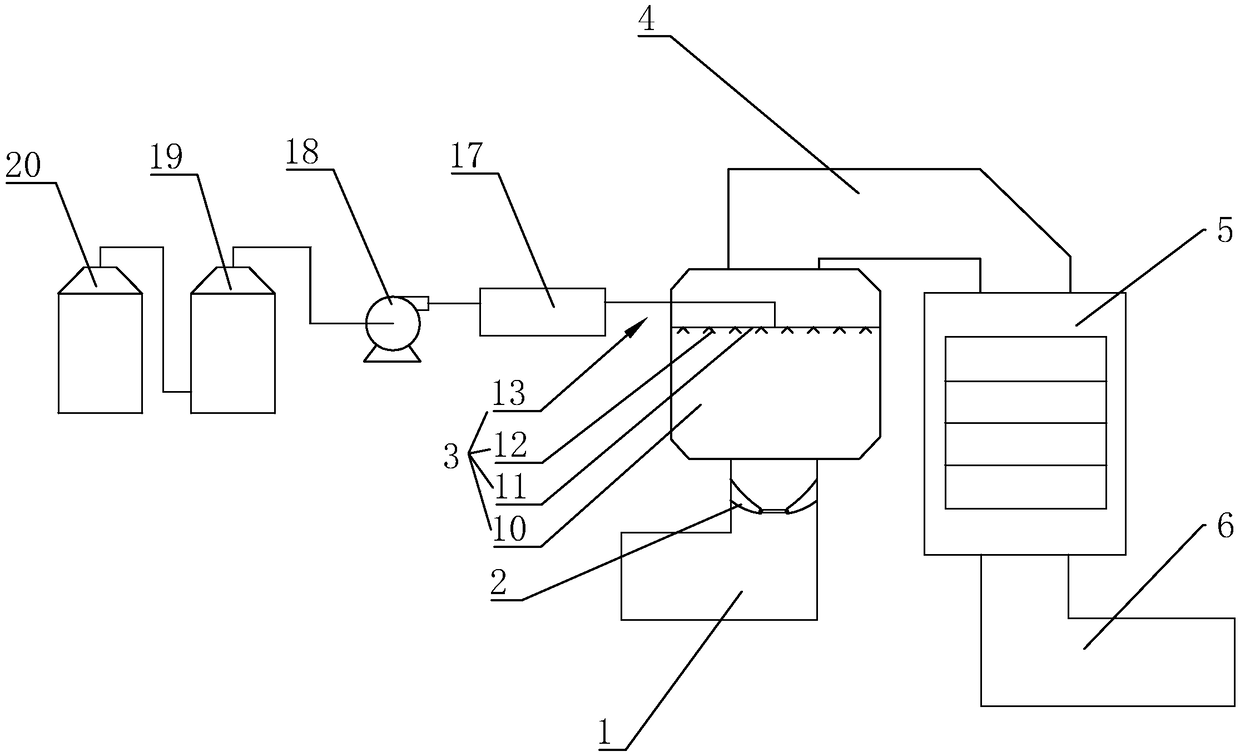
[0043] Such as figure 1 As shown, a flue gas swirling re-distributed denitrification reactor includes a flue gas inlet pipe 1 connected to each other in sequence, a swirl assembly 2 for guiding the flue gas, an ammonia injection mixing device 3, a connecting flue pipe 4, Catalytic reaction device 5 and flue gas outlet pipe 6.

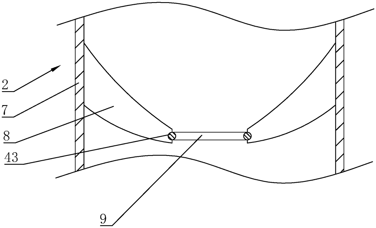
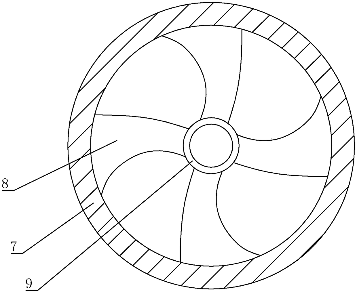
[0044] Such as figure 1 and figure 2 As shown, the swirl assembly 2 includes a first housing 7 , a deflector 8 and a mounting plate 9 . The first shell 7 is a hollow cylinder. One end of the flue gas inlet pipe 1 is connected to the boiler outlet, and the other end is fixedly connected to the first casing 7 . Such as image 3 and Figure 4 As shown, the deflectors 8 are in the shape of spiral fan blades. The deflectors 8 are fixedly connected to the inner wall of the first casing 7 and there are four deflectors 8 along the circumference of the first casing 7 . All the deflectors 8 have the same rotation direction. The angle α between the tangent...

Embodiment 2

[0050] The difference between Embodiment 2 and Embodiment 1 is that, as Figure 7 As shown, the mounting plate 9 is located at the lower end of the deflector 8 and the section of the mounting plate 9 is arranged in a ring shape. The lower end of the mounting plate 9 is connected to the rod 21 , the connecting rod 21 is L-shaped, and the connecting rod 21 is fixedly connected to the mounting plate 9 and the inner wall of the first housing 7 . Two connecting rods 21 are arranged symmetrically along the axis of the mounting plate 9 . Furthermore, the mounting plate 9 is stably fixed in the first housing 7 .

[0051] Such as Figure 7 and Figure 8 As shown, the outer wall of the mounting plate 9 is fixed with rotating shafts 22 along its radial direction, and several rotating shafts 22 are provided along the circumferential direction of the mounting plate 9 and each rotating shaft 22 corresponds to a deflector 8 . A connecting plate 44 is fixed on the end of the deflector 8 c...

Embodiment 3

[0059] The difference between the third embodiment and the first embodiment is that, as shown in 12 , a dust collecting hopper 42 is provided on the bottom side of the flue gas inlet pipe 1 and the flue gas outlet pipe 6 respectively. During the flow of the flue gas, the particles in the flue gas can fall into the ash collecting hopper 42 when falling, which reduces the dust falling on the inner wall of the flue gas inlet pipe 1 and the inner wall of the flue gas outlet pipe 6, and then enters the next wave. Probability in smoke.


PUM


Abstract

The invention relates to the field of environmental protection devices, and concretely discloses a cyclone redistribution denitration reactor for flue gas. The cyclone redistribution denitration reactor comprises a flue gas inlet tube, a cyclone assembly for guiding flue gas, an ammonia spraying and mixing device, a connecting flue gas tube, a catalytic reaction device and a flue gas outlet tube which are sequentially interconnected, the cyclone assembly comprises a first shell, the flow guiding plates and a mounting plate, the flow guiding plates have a spiral fan blade shape, the flow guiding plates are connected to the inner wall of the first shell, and are arranged along the circumferential direction of the first shell, the quantity of the flow guiding plates is more than one, the rotating directions of all the flow guiding plates are same to each other, the mounting plate is positioned among all the flow guiding plates, and the mounting plate is fixedly connected to one ends, facing the center of the first shell, of all the flow guiding plates. Flue gas enters the cyclone assembly through the flue gas inlet tube, and moves along the flow guiding plates to form a uniform-rotating flue gas flow, so the flue gas is in a uniformly distributed state when moving to the ammonia spraying and mixing device, thereby the flue gas is well contacted and reacted with a reaction solutionsprayed by the ammonia spraying and mixing device, dead angles are reduced, and the denitration efficiency is improved.

Description

technical field [0001] The invention relates to the field of environmental protection equipment, in particular to a flue gas swirling re-distributed denitrification reactor. Background technique [0002] The importance of preventing environmental pollution has been sharply raised as a worldwide problem. With the development of modern industrial production and the improvement of living standards, air pollution has become a matter of great concern to people. [0003] The existing flue gas denitrification technologies mainly include dry method (selective catalytic reduction flue gas denitrification, selective non-catalytic reduction method denitrification) and wet method. Compared with wet flue gas denitrification technology, the main advantages of dry flue gas denitrification technology are: low basic investment, simple equipment and process, high efficiency of NOX removal, no waste water and waste treatment, not easy to cause secondary pollution secondary pollution. Select...

Claims


Application Information

Patent Timeline
Patent Type & Authority Applications(China)
IPC IPC(8): B01D53/90B01D53/86B01D53/56
CPCB01D53/8631B01D53/90B01D2258/0283
Inventor 赵博宣学伟陈小利蒋成军范德华顾一飞
Owner ZHEJIANG TUNA ENVIRONMENTAL SCI & TECH
Why Eureka
Try Eureka