[0016] The present invention will be further explained below in conjunction with the drawings.
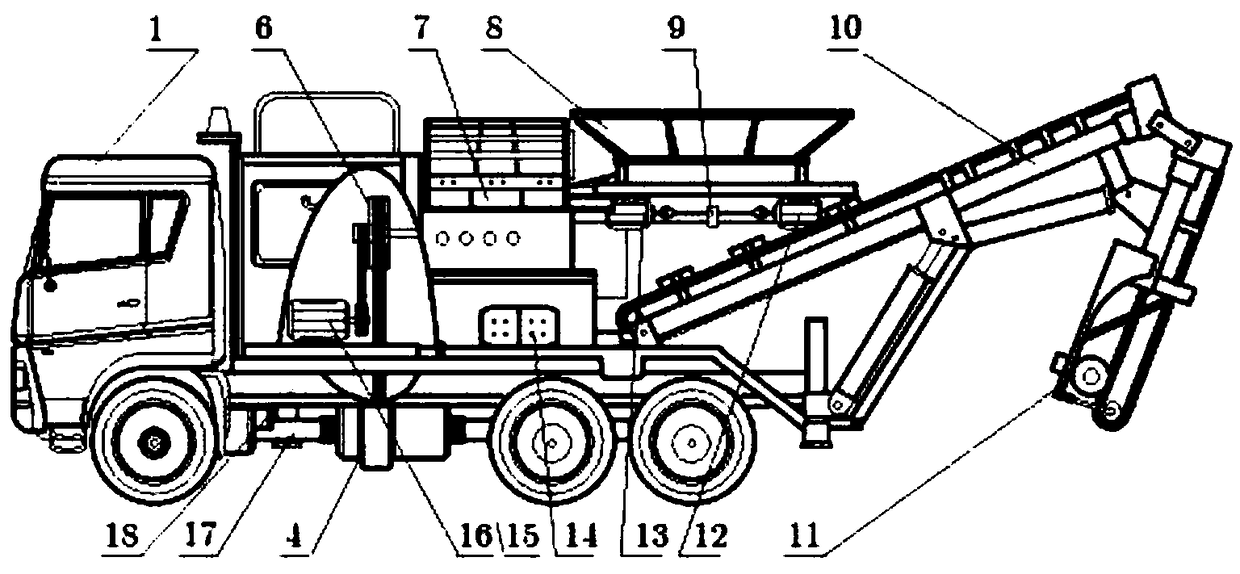
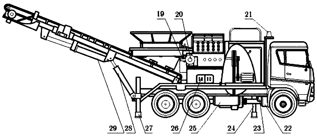
[0017] Such as Figure 1 to Figure 5 As shown, a self-propelled aggregate crusher with remote automatic control system is mainly composed of heavy truck 1, aggregate crusher module, electrical control module, power switch module 4, hydraulic action module, truck rear axle input shaft 15, The front section 17 of the truck main shaft and the truck frame 18 are composed; the aggregate crusher module is composed of the crusher pulley 6, the hammer crusher 7, the feeding device 8 and the discharging device 10; the hammer crusher 7 is installed on the truck frame Above 18, the crusher pulley 6 is connected to the power switching module 4, the feeding device 8 is mounted on one side of the hammer crusher 7 through a hinge, and the discharging device 10 is mounted on the tail of the truck frame 18 through a hinge.
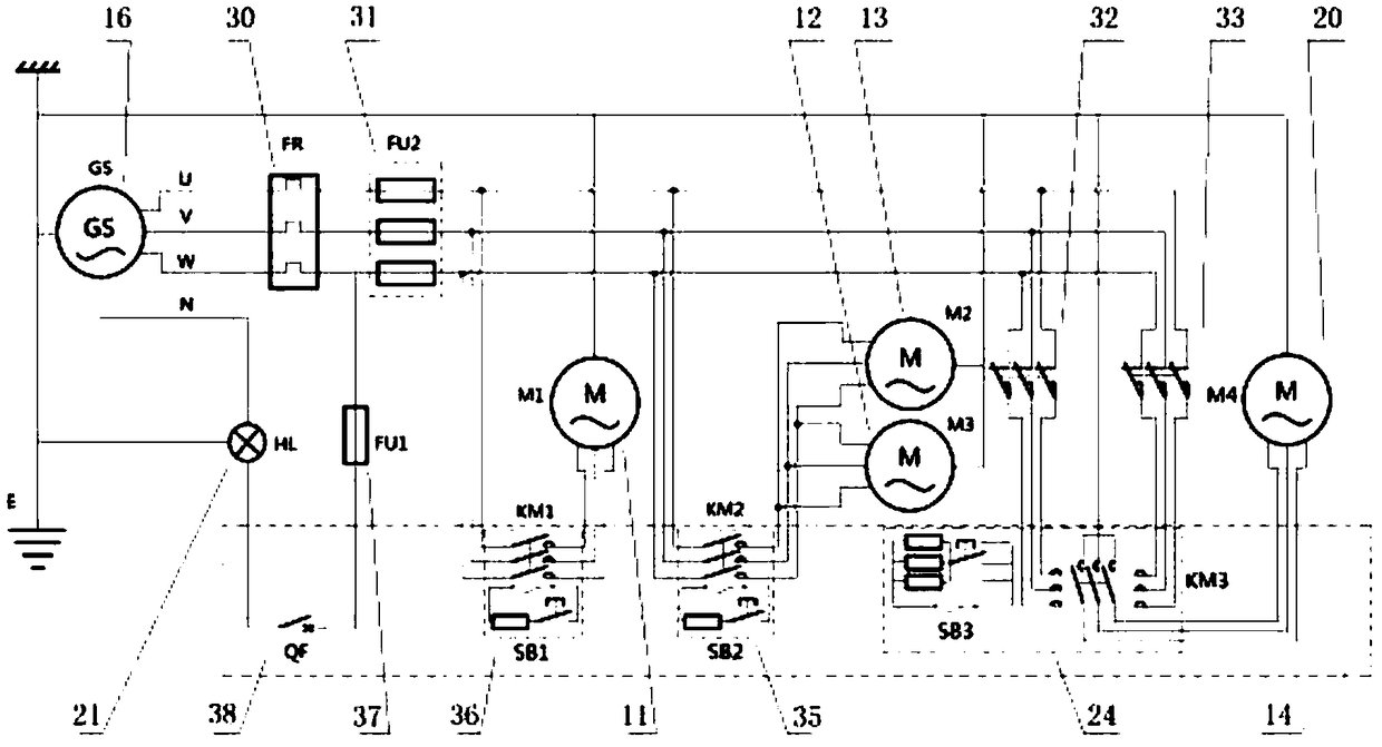
[0018] The electrical control module is composed of compound excitation three-phase synchronous generator 16, vibration eccentric 9, first vibration motor 12, second vibration motor 13, feeding device control motor 20, worm gear 19, discharge device control motor 11, and working Warning light 21, electrical system remote control panel 14, thermal relay 30, motor fuse 31, forward rotation limit switch 32, flip limit switch 33, feeding device control motor contactor 34, vibration motor contactor 35, conveyor belt The motor contactor 36, the warning light fuse 37 and the air switch 38 are composed. The compound excitation three-phase synchronous generator 16 is connected to the crusher pulley 6. The first vibration motor 12 and the second vibration motor 13 are coaxially installed on the feeding device 8. At the bottom, jointly drive the vibrating eccentric 9; the feeding device control motor 20 is installed under the hinge of the feeding device, and is connected to the feeding device 8 through the turbine and worm pair 19; the working warning light 21 is installed on the top of the heavy truck 1; the electrical system is remotely controlled Panel 14 is installed on the left side of truck frame 18; compound-excited three-phase synchronous generator 16, first vibration motor 12, second vibration motor 13, feeding device control motor 20, discharging device control motor 11, working warning light 21 It is connected to the remote control panel 14 of the electrical system through a switch circuit. The work warning lamp 21, the first vibration motor 12, the second vibration motor 13, and the discharging device control motor 11 in the electrical control module are respectively controlled by independent switches; in preparation for work, the feeding device control motor 20 is controlled by a worm gear The auxiliary 19 drives the feeding device 8 to rotate in the horizontal plane to the normal working form; in the working state, the work warning light 21 is turned on, the first vibration motor 12 and the second vibration motor 13 drive the vibration eccentric 9 to rotate, and the discharge device controls The motor 11 drives the discharging device 10 to operate; in the transportation state, the feeding device controls the motor 20 to drive the feeding device 8 through the worm gear 19 to rotate in the horizontal plane to the retracted state, the first vibration motor 12, the second vibration motor 13 , The discharging device controls the motor 11 and the working warning lamp 21 to cut off power.
[0019] The power switching module 4 consists of an input coupling 39, an input spline shaft 40, an input end cover 41, a housing 42, an input bearing sleeve 43, a switch output pulley 44, a gear ring 45, and a spline collar 46, fork 47, input spline hub gear 48, locking collar 49, lock nut 50, fork shaft guide ring 51, fork shaft 52, fork shaft positioning locking buckle 53, fork handle 54 , Output end coupling 55, output end spline shaft 56, output end cover 57, output end thrust bearing 58, output end bearing sleeve 59, cylindrical roller bearing 60, spline collar 61, output end spline Hub gear 62, lock collar 63, lock nut 64, output end internal gear engagement sleeve 65, pulley internal gear engagement sleeve 66, axial thrust bearing 67, cylindrical roller bearing 68, thrust bearing 69 and thrust bearing 70 Composition; the input coupling 39 of the power switching module 4 is connected to the front section 17 of the truck main shaft, the switch output pulley 44 is connected to the compound three-phase synchronous generator 16, and the output coupling 55 of the power switching module 4 is connected to the truck The rear axle input shaft 15 is connected; the power switch module 4 is controlled by the shift fork shaft 52 to move the shift fork 47 to the output end internal gear engagement sleeve 65 and the pulley internal gear engagement sleeve 66 in the ring gear 45, the input end spline hub gear 48 and The spline hub gear 62 at the output end slides up to realize the switching of the torque of the front section 17 of the truck main shaft between the compound excitation three-phase synchronous generator 16 and the truck rear axle input shaft 15.
[0020] The hydraulic action module consists of gearbox power take-off 22, hydraulic pump 23, hydraulic oil tank 25, hydraulic pump 23, primary hydraulic lever 28, secondary hydraulic lever 29, front hydraulic column 24, rear hydraulic column 27, and remote hydraulic system Control panel 26, one-way valve 71, relief valve 72, first one-way throttle valve 73, second one-way throttle valve 74, third one-way throttle valve 75, fourth one-way throttle valve 76, Rear hydraulic column control reversing valve 77, front hydraulic column control reversing valve 78, secondary hydraulic lever reversing valve 79, primary hydraulic lever reversing valve 80, back pressure valve 81, oil return filter 82 and The oil inlet filter 83 is composed; the hydraulic oil tank 25 is mounted on the bottom of the truck frame 18; the hydraulic pump 23 is mounted on the power take-off port 22 of the truck transmission; the front hydraulic column 24 is mounted on the middle front part of the truck frame 18, and the rear The row of hydraulic columns 27 are installed at the rear of the truck frame 18 to stably support the heavy truck 1, and the primary hydraulic lever 28 and the secondary hydraulic lever 29 are installed on the discharge device 10 to control the opening and folding actions of the discharge device. The system remote control panel 26 is installed on the left side of the truck frame 18, the hydraulic oil tank 25, the hydraulic pump 23, the front hydraulic column 24, the rear hydraulic column 27, the primary hydraulic lever 28, and the secondary hydraulic lever 29 pass valve oil. Road connected. In the working state of the crusher, the hydraulic system can control the front hydraulic column 24 and the rear hydraulic column 27 to extend to lift and support the heavy truck 1, and the primary hydraulic rod 28 and the secondary hydraulic rod 29 to extend to support the discharge Device 10; in the transportation state, the front hydraulic column 24, the rear hydraulic column 27, the first-level hydraulic rod 28 and the second-level hydraulic rod 29 are all slowly retracted to lower the center of gravity and reduce the volume.
[0021] The above are only preferred embodiments of the present invention. It should be pointed out that for those of ordinary skill in the art, several improvements can be made without departing from the principle of the present invention, and these improvements should also be regarded as the present invention. protected range.