Drying device for weaving
A drying device and drying box technology, applied in textile and papermaking, textile material processing, liquid/gas/vapor removal with squeeze rollers, etc., can solve the problem of low work efficiency, slow drying speed and unsafe production and other problems to achieve the effect of speeding up drying speed, improving safety and improving work efficiency
- Summary
- Abstract
- Description
- Claims
- Application Information
AI Technical Summary
Problems solved by technology
Method used
Image

Examples
Embodiment 1
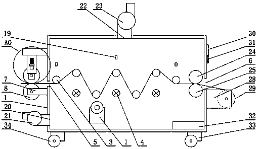
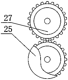
[0028] see Figure 1-4 , the present invention provides a technical solution: a drying device for textiles, comprising a drying box 1, a squeeze roller 2, a driving roller 3, and a heating pipe 4, and cloth inlets 5 are respectively arranged on both sides of the outer surface of the drying box 1 With the cloth outlet 6, the cloth inlet 5 and the cloth outlet 6 are arranged on the same height of the drying box 1, and the position on the drying box 1 is opposite, and the outer wall of the drying box 1 located at the lower end of the cloth inlet 5 is fixedly connected with a No. 1 U A fixed roller 8 is arranged between the plate 7 and the No. 1 U-shaped plate 7, and a connecting plate 9 is fixedly connected to the outer wall of the drying box 1 corresponding to the upper end of the fixed roller 8, and the other end of the connecting plate 9 is fixedly connected downward to a No. 2 U Type plate 10, the No. 2 U-shaped plate 10 is provided with a chute 11, the inside of the chute 11...
Embodiment 2
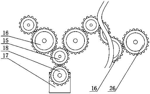
[0039] see Figure 1-4 , the working principle of the present invention is: when in use, the textile cloth enters from one end of the cloth inlet 5, and before entering, the textile cloth first passes through the fixed roller 8 and the squeeze roller 2, and when passing through the fixed roller 8 and the squeeze roller 2, it is fixed The roller 8 and the squeeze roller 2 roll relatively between the No. 1 U-shaped plate 7 and the No. 3 U-shaped plate 14 respectively, and the squeeze roller 2 will receive the downward force of the spring 13 on the slider 12 during the rolling process. The block 12 slides downward in the chute 11 under the active force so as to give a downward pressure to the squeeze roller 2, so that the textile cloth passing through the squeeze roller 2 squeezes out moisture, and the textile fabric after squeezing the moisture continues to pass through the drive roller 3 is transmitted to the cloth outlet 6, the driving motor 17 inside the drying box 1 drives t...
Embodiment 3
[0042] The drive motor control switch, the blower control switch, and the exhaust fan control switch can be independently controlled by the operation button 31, and the operation button 31 is connected with the micro-processing unit 32 for sending relevant instructions, driving the motor control switch, the blower control switch, and the exhaust fan control switch. Machine control switch is connected with drive motor 17, air blower 21, air exhauster 23 respectively, and drive motor 17, air blower 21, air exhauster 23 are controlled; The control mode to drive motor 17 is to directly operate by drive motor control switch, or Send the command to the micro-processing unit 32 by operating the button 31, and the micro-processing unit 32 transmits the work information to the drive motor control switch after analyzing and processing the command, and the drive motor control switch controls the working state of the drive motor 17 according to the received work information; The display sc...
PUM
 Abstract
Description
Claims
Application Information
 - R&D
- Intellectual Property
- Life Sciences
- Materials
- Tech Scout
- Unparalleled Data Quality
- Higher Quality Content
- 60% Fewer Hallucinations
Browse by: Latest US Patents, China's latest patents, Technical Efficacy Thesaurus, Application Domain, Technology Topic, Popular Technical Reports.
© 2025 PatSnap. All rights reserved.Legal|Privacy policy|Modern Slavery Act Transparency Statement|Sitemap|About US| Contact US: help@patsnap.com