Semi-assembled prefabricated beam and preparation method and design method thereof

A technology of prefabricated assembly and steel beams, applied in the direction of joists, girders, truss beams, etc., can solve the problems of difficult realization of steel structure houses and high maintenance costs, so as to reduce the lateral displacement response, reduce the overall cost, and save costs Effect

Pending Publication Date: 2019-01-11
ARCHITECTURAL DESIGN INST FUKIEN PROV
View PDF5 Cites 4 Cited by
  • Summary
  • Abstract
  • Description
  • Claims
  • Application Information

AI Technical Summary

Problems solved by technology

Although anti-corrosion and fire-resistant coating can be used for treatment, regular maintenance is required within the design service life, which is almost difficult to achieve for steel structure houses, and the later maintenance costs are relatively high

Method used


Image

  • Semi-assembled prefabricated beam and preparation method and design method thereof
  • Semi-assembled prefabricated beam and preparation method and design method thereof
  • Semi-assembled prefabricated beam and preparation method and design method thereof

Examples


Embodiment 1

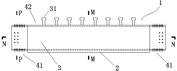
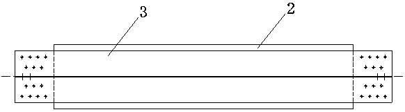
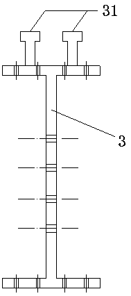
[0033] Embodiment one: if Figure 1~4 As shown, a semi-combined prefabricated assembled beam, the semi-combined prefabricated assembled beam 1 includes an H-shaped steel beam 3 and an outer cladding protective layer 2, and the outer cladding protective layer 2 is arranged on the H-shaped steel beam 3 The outer surface of the H-shaped steel beam 3 is provided with bolt holes on the flanges and webs at both ends, and the two ends of the H-shaped steel beam 3 are respectively reserved with end connection nodes for connecting steel columns. Covering area 41, the upper flange of the H-shaped steel beam 3 is welded with studs 31, and the outer surface of the upper flange of the H-shaped steel beam 3 is reserved with an uncoated area of ​​the upper connection node for connecting the concrete floor 42.

[0034] In this first embodiment, the outer cladding protective layer 2 is preferably but not limited to a reinforced concrete outer cladding 2, and the outer cladding protective laye...

Embodiment 2

[0048] Embodiment two: if Figure 5 As shown, the difference between it and the first embodiment is that the grooves on both sides of the H-shaped steel beam 3 are provided with thermal insulation filling layers 23 .

[0049] In the second embodiment, the thermal insulation filling layer 23 is preferably but not limited to the foam thermal insulation layer 23 . During manufacture, the foam insulation layer 23 is filled in the grooves on both sides of the H-shaped steel beam 3, and then the reinforced concrete layer is covered.

Embodiment 3

[0050] Embodiment three: as Image 6 As shown, the difference between it and the second embodiment is that the steel bar used in the reinforced concrete outer cladding layer 2 extends above the studs 31, that is, the stirrups of the outer cladding protective layer 2 are directly extended into the floor area. During construction, the pegs 31 and stirrups extending into the floor slab are poured on-site in the floor slab, so that the floor slab is reliably connected with the H-shaped steel beam 3 and the outer cladding protection layer 2 into one. Certainly, if the steel wire mesh concrete outer cladding is selected as the outer cladding protective layer 2 , the steel wires of the steel wire mesh concrete outer cladding may also extend above the pegs 31 .


PUM


Abstract

The invention discloses a semi-assembled prefabricated beam and a preparation method and design method thereof. The semi-assembled prefabricated beam comprises an H-shaped steel beam and an outer protection coating. The outer protection coating is arranged on the outer surface of the H-shaped steel beam. Flanges of two ends of the H-shaped steel beam and a web are provided with bolt holes. Two ends of the H-shaped steel beam are respectively provided with end connection joint uncoated zones for connecting a steel column. The upper flange of the H-shaped steel beam is welded to a bolt. The outer surface of the upper flange of the H-shaped steel beam is provided with an upper connection joint uncoated zone for connecting a concrete floor. The semi-assembled prefabricated beam retains the load and construction advantages of the traditional fabricated steel beam, solves the problem that the conventional assembled steel structural beam needs anti-corrosion and fireproof treatment and regular maintenance, reduces the comprehensive cost of the steel structure system and improves the overall rigidity, anti-seismic properties and construction and use convenience of the steel structure.

Description

technical field [0001] The invention relates to the field of prefabricated buildings, in particular to a semi-combined prefabricated prefabricated beam and its manufacturing method and design method. Background technique [0002] Prefabricated steel structure buildings have light weight, high strength, good seismic performance, low foundation cost, high degree of industrialization, convenient installation and construction, short construction period, fast investment recovery, green energy saving and environmental protection, recyclable materials, flexible residential layout and Features and advantages such as high housing rate. Although the steel structure has some of the advantages mentioned above, its corrosion resistance and fire resistance are more prominent, especially for steel structure residences. Although anti-corrosion and fire-resistant coatings can be used for treatment, regular maintenance is required within the design service life, which is almost difficult to ...

Claims


Application Information

Patent Timeline
Patent Type & Authority Applications(China)
IPC IPC(8): E04C3/04E04B1/62E04B1/94
CPCE04B1/62E04B1/94E04C3/04E04C2003/0452
Inventor 曾志攀刘金玲黄冀卓
Owner ARCHITECTURAL DESIGN INST FUKIEN PROV
Why Eureka
Try Eureka