
High-strength cutterhead of pipe-jacking heading machine

A pipe jacking machine, high-strength technology, applied in mining equipment, earthwork drilling, tunnels, etc., can solve problems such as affecting the ejection effect, difficulty in sharing the jacking pressure of spokes, and weakened cutting force of the cutter head

Inactive Publication Date: 2019-01-11
淮南中泰矿山装备制造有限公司
View PDF23 Cites 1 Cited by
  • Summary
  • Abstract
  • Description
  • Claims
  • Application Information

AI Technical Summary

Problems solved by technology

[0002] Pipe jacking construction is a pipeline burying construction technology, and the cutter head is the primary tool for the comprehensive excavation of pipelines by the pipe jacking machine, but the support strength of the spokes (i.e. spokes) in the cutter head used in the prior art is not ideal, for example : The patent application number is [CN201520157352.8] for the cutter head of the large-diameter earth pressure balance pipe jacking machine. Only a plurality of spokes are installed between the outer peripheral retainer and the hub, but it is difficult to improve the support strength of the spokes, so that it is difficult to share the top of the spokes. In addition, the edge of the above-mentioned application also lacks a soil extrusion structure, and the soil on the edge of the cutter head cannot be squeezed out during the jacking process, thereby affecting Its ejection effect, so it needs to be improved

Method used


Image

  • High-strength cutterhead of pipe-jacking heading machine
  • High-strength cutterhead of pipe-jacking heading machine
  • High-strength cutterhead of pipe-jacking heading machine

Examples


Embodiment Construction

[0020] The following will clearly and completely describe the technical solutions in the embodiments of the present invention with reference to the accompanying drawings in the embodiments of the present invention. Obviously, the described embodiments are only some, not all, embodiments of the present invention. Based on the embodiments of the present invention, all other embodiments obtained by persons of ordinary skill in the art without making creative efforts belong to the protection scope of the present invention.

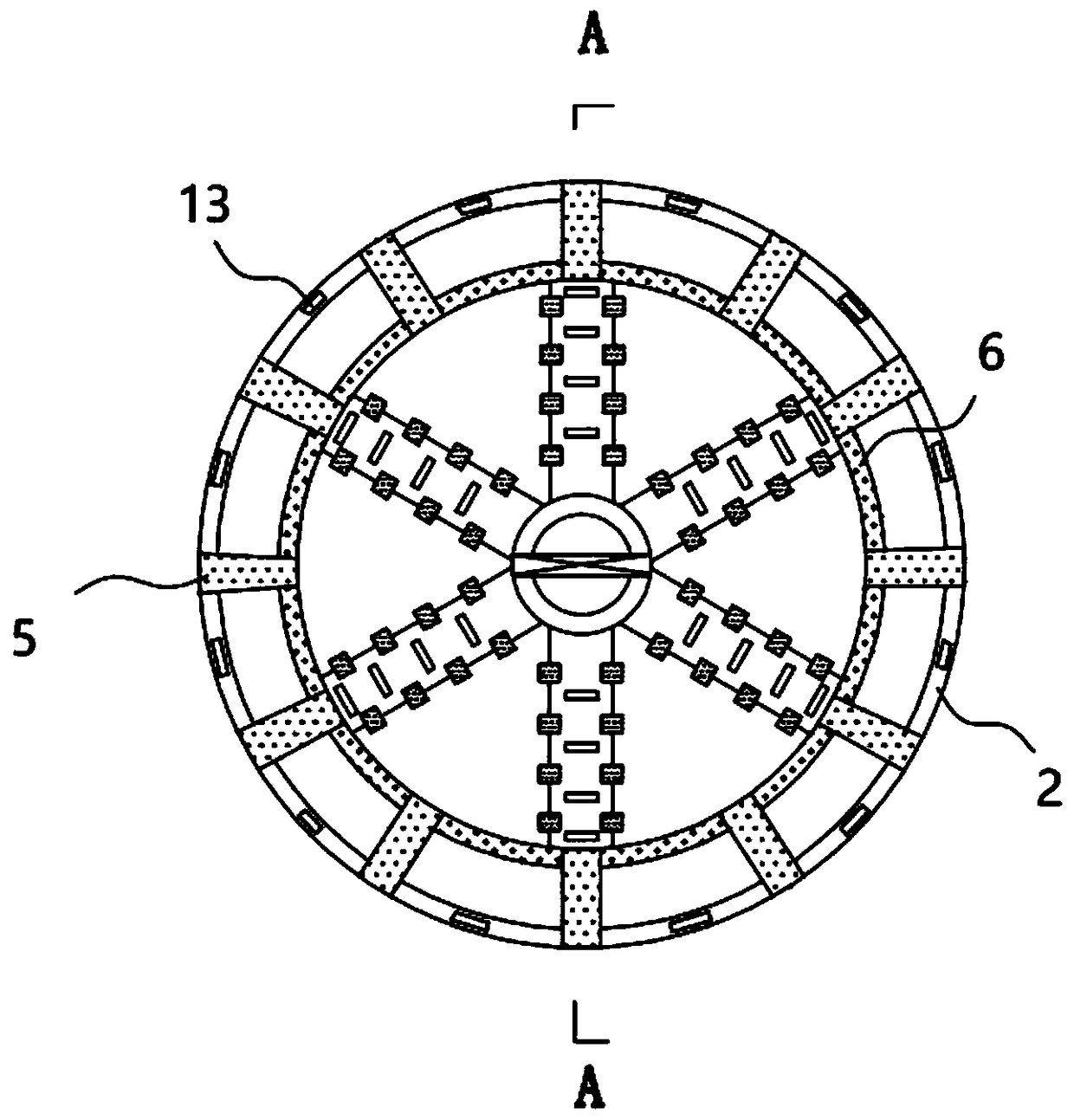
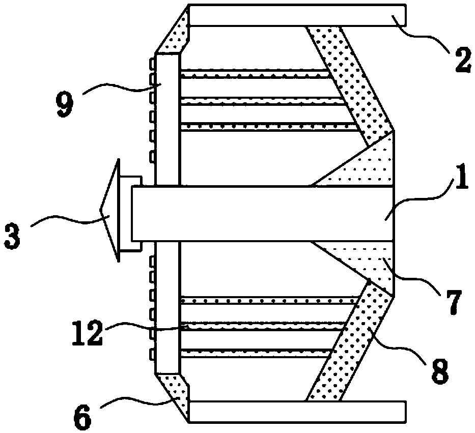
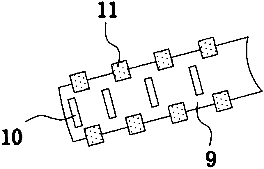
[0021] see Figure 1-5 , the present invention provides a technical solution: a high-strength cutterhead of a pipe jacking machine, including a hub 1 and an outer retainer 2 centered on the hub 1, and the peripheral protection of the cutterhead can be performed through the setting of the outer retainer 2, To reduce the overall wear of the cutter head, the front end of the hub 1 is equipped with an axially protruding main cutter head 4, through the setting of t...


PUM

PropertyMeasurementUnit
Angleaaaaaaaaaa

Abstract

The invention discloses a high-strength cutterhead of a pipe-jacking heading machine, which comprises a hub and an outer guard ring taking the hub as a center, and is characterized in that the front end of the hub is provided with an axially protruding main cutter head, wear-resistant welding rods are obliquely connected at equal intervals by taking the hub as a center point at the front side of the outer guard ring, reinforcing ribs arranged in a ring-shaped manner are connected between two adjacent wear-resistant welding rods, the outer wall of the hub is connected with four triangular support frames arranged at equal intervals, and an obliquely arranged reinforcing steel plate is welded between the inclined surface of each triangular support frame and the inner wall of the outer guard ring. According to the invention, the outer wall of the hub is connected with four triangular support frames arranged at equal intervals, the obliquely arranged reinforcing steel plate is welded between the inclined surface of each triangular support frame and the inner wall of the outer guard ring, and the strength of the whole cutterhead and the pressure resistance during jacking can be improvedthrough the cooperation of the triangular support frames and the reinforcing steel plates.

Description

technical field [0001] The invention relates to the technical field of cutter heads of pipe jacking machines, in particular to a high-strength cutter head of pipe jacking machines. Background technique [0002] Pipe jacking construction is a pipeline burying construction technology, and the cutter head is the primary tool for the pipe jacking machine to fully excavate the pipeline, but the support strength of the spokes (i.e. spokes) in the cutter head used in the prior art is not ideal, for example : The patent application number is [CN201520157352.8] for the cutter head of the large-diameter earth pressure balance pipe jacking machine. Only a plurality of spokes are installed between the outer peripheral retainer and the hub, but it is difficult to improve the support strength of the spokes, so that it is difficult to share the top of the spokes. In addition, the edge of the above-mentioned application also lacks a soil extrusion structure, and the soil on the edge of the ...

Claims


Application Information

Patent Timeline
IPC IPC(8): E21D9/10
CPCE21D9/1006
Inventor 甘红兵
Owner 淮南中泰矿山装备制造有限公司
Learn More