Built-in solenoid valve type variable damping shock absorber

A technology of solenoid valves and shock absorbers, applied in the direction of shock absorbers, springs/shock absorbers, shock absorbers, etc., can solve the problem of reducing the response speed and integration degree of variable damping shock absorbers, solenoid valves and shock absorbers Problems such as the separation of the main body of the device and the increase of the length of the liquid flow path have been achieved to achieve the effects of compact structure, reduced failure rate, and short stroke path

Pending Publication Date: 2019-01-11
XGM CORP LTD
View PDF0 Cites 10 Cited by
  • Summary
  • Abstract
  • Description
  • Claims
  • Application Information

AI Technical Summary

Problems solved by technology

On the one hand, the peripheral solenoid valve is completely protected by the solenoid valve shell, which has extremely high requirements on the strength of the solenoid valve shell; at the same time, the connection between the solenoid valve and the main part of the shock absorber in this type of structure is often relatively weak. Under the influence of internal hydraulic pressure and external vibration, the failure rate of the solenoid valve is high and there is a hidden danger of separation of the solenoid valve and the main part of the shock absorber
On the other hand, the structure of the peripheral solenoid valve undoubtedly increases the length of the liquid flow path and reduces the response speed and integration degree of the variable damping shock absorber.

Method used


Image

  • Built-in solenoid valve type variable damping shock absorber
  • Built-in solenoid valve type variable damping shock absorber
  • Built-in solenoid valve type variable damping shock absorber

Examples


Embodiment Construction

[0019] The present invention will be further described below in conjunction with the accompanying drawings and specific implementation methods (embodiments), but it is not used as a basis for limiting the present invention.

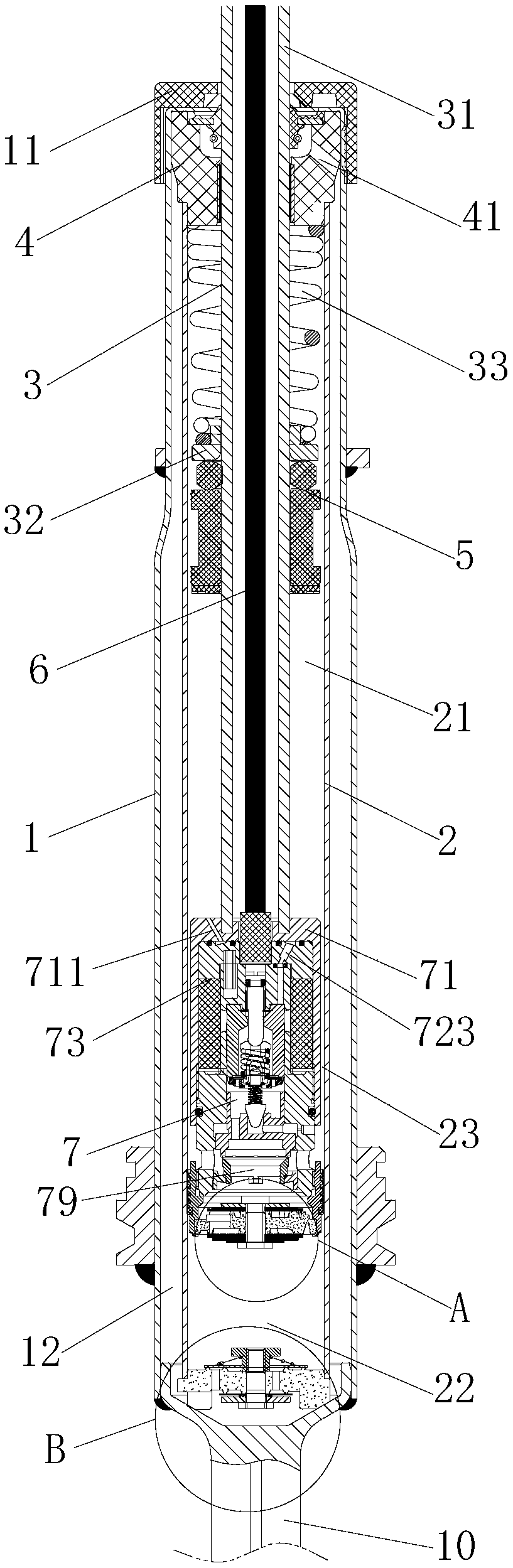
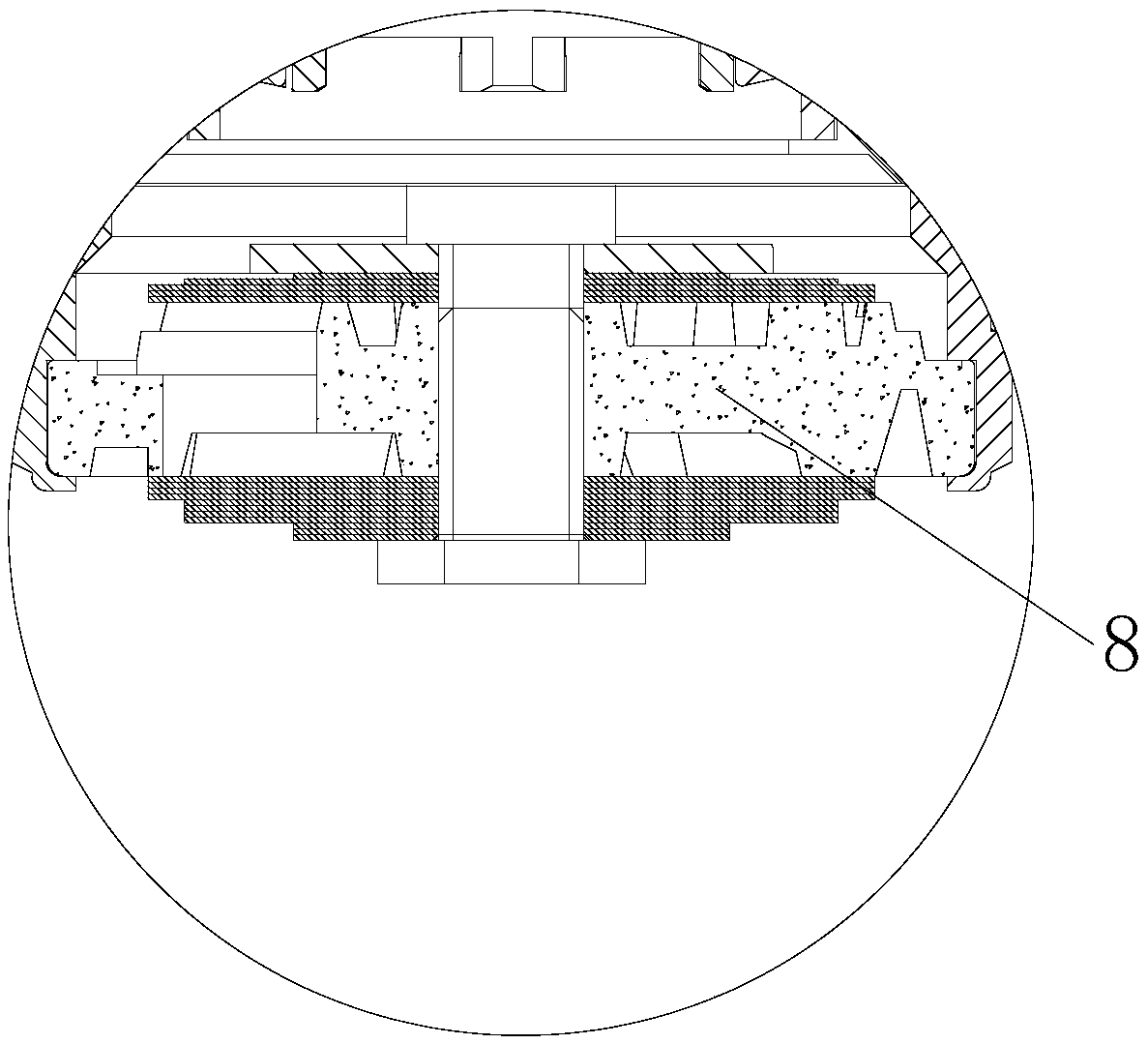
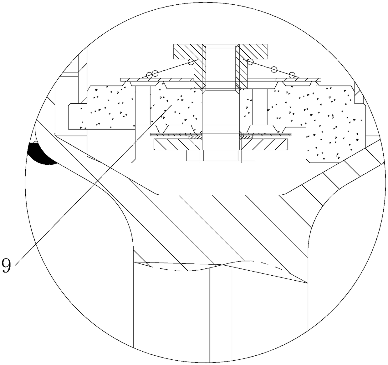
[0020] Such as Figure 1 to Figure 4 The shown built-in electromagnetic valve type variable damping shock absorber is characterized in that it includes a liquid storage cylinder 1, a working cylinder 2 is arranged in the liquid storage cylinder 1, and a working cylinder 2 is formed between the liquid storage cylinder 1 and the working cylinder 2. C liquid flow chamber 12, the working cylinder 2 is provided with a piston rod assembly 3 that can slide relative to it; the lower end of the liquid storage cylinder 1 is connected to the upper end of the coupling fork 10 to form a seal, and the upper end is sleeved with an end cover 11, There is an oil seal guide assembly 4 inside; the upper end of the working cylinder 2 is against the oil seal guide assembly 4,...


PUM


Abstract

The invention discloses a built-in solenoid valve type variable damping shock absorber which comprises a liquid storage barrel. A work cylinder is arranged in the liquid storage barrel. A C-shaped flow cavity is formed between the liquid storage barrel and the work cylinder, and a piston rod assembly capable of sliding relative to the work cylinder is arranged in the work cylinder. The lower end of the liquid storage barrel and the upper end of a combination fork are connected to form sealing, the outer portion of the upper end of the liquid storage barrel is sleeved with an end cover, and anoil seal guide assembly is arranged in the liquid storage barrel. The upper end of the work cylinder abuts against the oil seal guide assembly. The piston rod assembly comprises a hollow piston rod, the upper end of the piston rod assembly stretches out from the upper end of the liquid storage barrel, and a built-in solenoid valve assembly is arranged at the tail end of the piston rod assembly andis connected with the piston rod assembly through a wire. The tail end of the built-in solenoid valve assembly is connected with a piston damping valve, and the work cylinder is divided by the pistondamping valve into a liquid flow cavity A and a liquid flow cavity B. The built-in solenoid valve type variable damping shock absorber has the advantages o f being high in safety, low in fault rate and long in service life. In addition, the built-in solenoid valve type variable damping shock absorber is high in integration degree, high in response speed and good in comfort.

Description

technical field [0001] The invention relates to the technical field of shock absorbers, in particular to variable damping shock absorbers. Background technique [0002] With the rapid development of China's economy, cars have become the most common means of transportation in people's daily life. In the use of automobiles, its safety and comfort are very important issues. Shock absorbers are a key factor in ensuring the safety and comfort of a car. Traditional shock absorbers cannot reasonably adjust the damping size according to specific road conditions, and cannot switch between comfort performance and handling performance. In response to this situation, a variable damping shock absorber, that is, a shock absorber that can adjust the size of the damping force, has appeared on the market. When the shock absorber with variable damping is working, the damping force can be adjusted by adjusting the opening of the solenoid valve. [0003] Because the price of the variable da...

Claims


Application Information

Patent Timeline
Patent Type & Authority Applications(China)
IPC IPC(8): F16F9/16F16F9/32F16F9/34
CPCF16F9/16F16F9/3207F16F9/34
Inventor 邓鹄孙林桥蒋木林何洪波
Owner XGM CORP LTD
Why Eureka
Try Eureka