
Hydraulic driving type push plate wave making test device under supergravity condition

A test device and super-gravity technology, applied in the field of hydraulically driven push plate wave-making test device, can solve the problems of small motor output torque, poor wave dissipation effect, inability to adjust the position and opening ratio of the wave dissipation plate, and achieve Enhanced reliability, simple form, and improved wave suppression efficiency

Pending Publication Date: 2019-01-11
ZHEJIANG UNIV
View PDF6 Cites 11 Cited by
  • Summary
  • Abstract
  • Description
  • Claims
  • Application Information

AI Technical Summary

Problems solved by technology

The existing wave-making device under the condition of supergravity generally uses a servo motor to drive the shaking plate to make waves. Due to the small output torque of the motor, it is only suitable for working conditions with low acceleration and low water depth; Install and fix the wave breaking plate on the other side of the model box to break the wave. If the wave condition changes during the test, the position and opening ratio of the wave breaking plate cannot be adjusted, resulting in poor wave breaking effect

Method used


Image

  • Hydraulic driving type push plate wave making test device under supergravity condition
  • Hydraulic driving type push plate wave making test device under supergravity condition
  • Hydraulic driving type push plate wave making test device under supergravity condition

Examples


Embodiment Construction

[0027] The present invention will be further described below in conjunction with the accompanying drawings and embodiments.

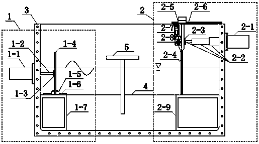
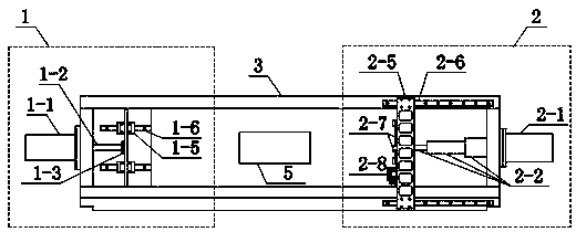
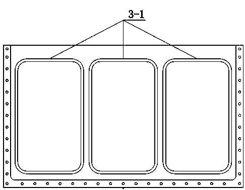
[0028] Such as figure 1 , figure 2 As shown, the device of the present invention includes a wave making unit 1, a wave dissipation unit 2, a model box 3, a seabed model 4, a marine structure model 5 and two sets of hydraulic drive systems; on the left side of the model box 3 filled with liquid The wave-making unit 1 is installed on the inner wall, and the wave-making hydraulic cylinder 1-1 of the wave-making unit 1 is installed on the left outer wall of the model box 3; The hydraulic cylinder 2-1 is installed on the outer wall of the right side of the model box 3; the groove formed between the bottom stopper 1-7 of the wave-making unit and the bottom stopper 2-9 of the wave-dissipating unit contains a seabed model 4 and a seabed model 4 The offshore structure model 5 is buried in the center; two sets of hydraulic drive systems installed outside the m...


PUM


Abstract

The invention discloses a hydraulic driving type push plate wave making test device under a supergravity condition. A wave making unit and a wave absorbing unit are respectively arranged at the innerwalls of the left side and the right side of a model box filled with liquid; a wave making hydraulic cylinder and a wave absorbing hydraulic cylinder are respectively arranged on the outer walls of the left side and the right side of the model box; a seabed model is arranged in a groove formed between a bottom stop block of the wave making unit and a bottom stop block of the wave absorbing unit; amarine structure model is buried in the seabed model; and two sets of hydraulic driving systems outside the model box respectively provide hydraulic power for the wave making hydraulic cylinder and the wave absorbing hydraulic cylinder through a centrifugal machine rotary joint. The device is suitable for high-frequency large wave making under the supergravity condition; the push plate type wavemaking is adopted, a power conversion system from a hydraulic driving system to a wave making plate has simpler and more reliable form than a conventional wheel disc type power conversion system driven by a servo motor; and during a test process, a distance between the wave absorbing plate and the wall of the model box and an aperture ratio of the wave absorbing plate are both adjustable, the simulation of waves under different working conditions can be met, and the wave absorbing efficiency is improved.

Description

technical field [0001] The invention relates to a geotechnical centrifugal simulation test device, in particular to a hydraulically driven pushing plate wave-making test device under supergravity conditions. Background technique [0002] Waves are one of the main environmental loads to be considered in the fields of marine engineering and coastal engineering. In order to study the interaction between the seabed foundation soil and marine structures under the action of waves, wave-making devices are needed to simulate waves in the test. In recent years, the development of geotechnical centrifuge simulation technology has made it possible to conduct wave tests under hypergravity conditions. The scale-down effect of geotechnical centrifuges can restore the prototype seabed stress field, which can reflect the field size compared with wave tests under normal gravity conditions. Wave-seabed foundation-marine structure interaction problem. [0003] However, as the marine developm...

Claims


Application Information

Patent Timeline
IPC IPC(8): G01M10/00
CPCG01M10/00
Inventor 朱斌李俊超孔德琼任杰吴雷晔陈云敏
Owner ZHEJIANG UNIV
Learn More