
A mechanical device for transporting silicon wafers

A mechanical device and silicon chip technology, applied in the direction of conveyor objects, transportation and packaging, electrical components, etc., can solve the problems of prolonging the invalid time of the silicon chip manufacturing process, complicated transmission control, and reducing work efficiency, so as to expand the scope of use and Application scenarios, simple and compact mechanism, and the effect of improving efficiency

Active Publication Date: 2019-01-11
BEIJING U PRECISION TECH
View PDF4 Cites 7 Cited by
  • Summary
  • Abstract
  • Description
  • Claims
  • Application Information

AI Technical Summary

Problems solved by technology

[0003] Now the most widely used is a three-fold arm robot. This type of robot uses three joint structures of the main arm, the auxiliary arm and the wrist to connect the fork claws. Due to the many joints of the three-fold arm manipulator, there are problems of drooping and shaking at the end, and the transmission control is relatively complicated.
There is also a newly developed single-arm single-fork manipulator. Although this manipulator can avoid the complexity of the joints, it has the same defect as the three-fold arm manipulator: they are only on the main arm. Connect a fork, when the fork picks up and sends silicon wafers, since only one fork is working, there will be a time gap in the process of picking or placing, so that the work efficiency will be greatly reduced and the silicon wafer will be lengthened. Inactive time of manufacturing process
In order to improve efficiency, at present, the double-fork manipulator mostly used in the world is a double-three folding arm structure to realize the double-piece fork, which increases the relative complexity.

Method used


Image

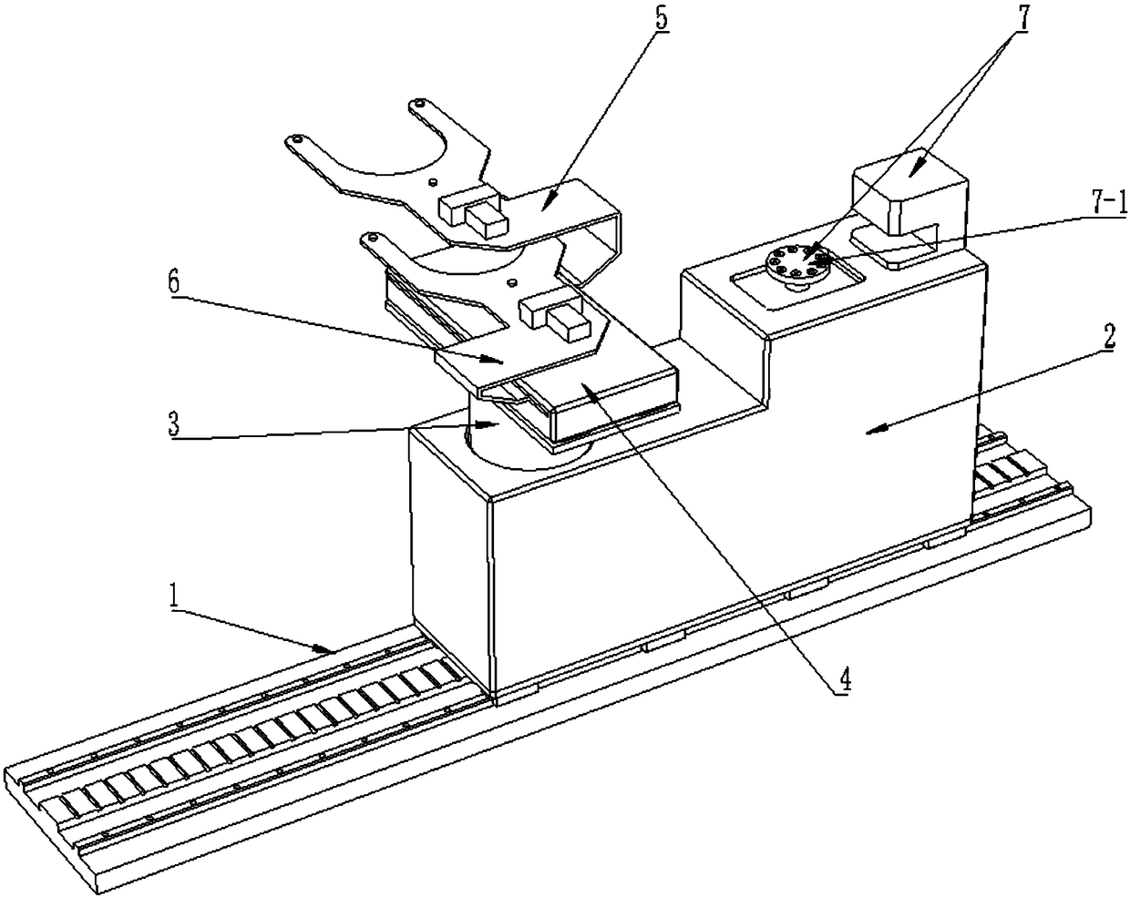
  • A mechanical device for transporting silicon wafers
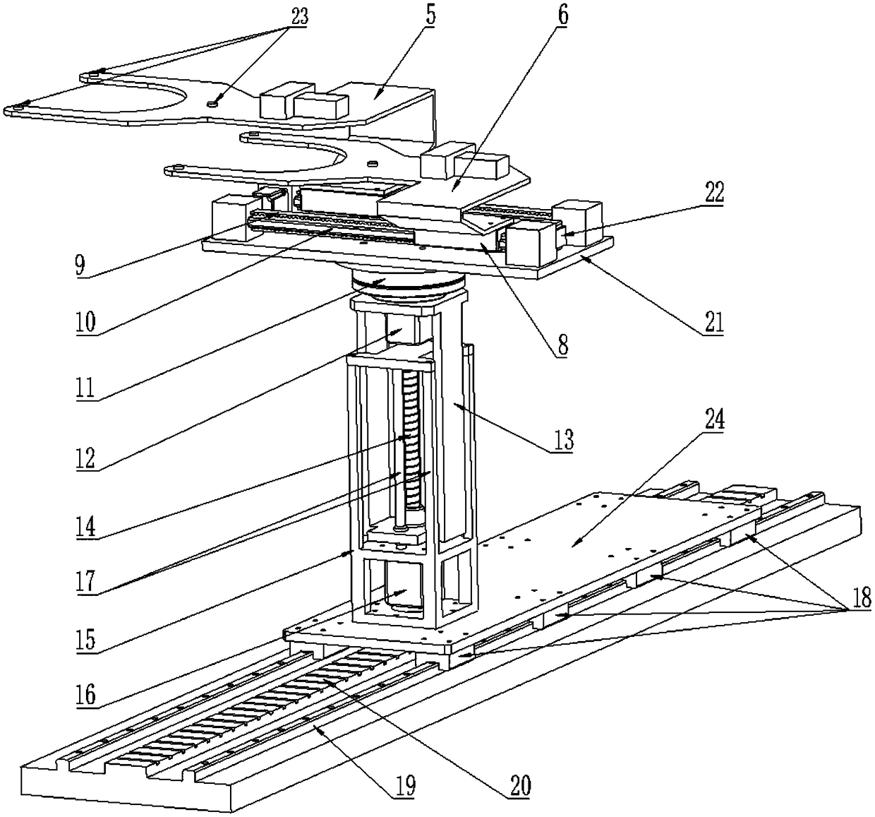
  • A mechanical device for transporting silicon wafers

Examples


Embodiment Construction

[0014] The technical solutions of the present invention will be clearly and completely described below in conjunction with the accompanying drawings. Apparently, the described embodiments are some of the embodiments of the present invention, but not all of them. Based on the embodiments of the present invention, all other embodiments obtained by persons of ordinary skill in the art without making creative efforts belong to the protection scope of the present invention.

[0015] In the description of the present invention, it should be noted that the terms "center", "upper", "lower", "left", "right", "vertical", "horizontal", "inner", "outer" etc. The indicated orientation or positional relationship is based on the orientation or positional relationship shown in the drawings, and is only for the convenience of describing the present invention and simplifying the description, rather than indicating or implying that the referred device or element must have a specific orientation, ...


PUM


Abstract

The invention relates to a mechanical device for transporting a silicon wafer, comprising an X-axis drive mechanism, Z-axis drive mechanism, Z-axis rotary drive mechanism, two sets of independent Y-axis drive mechanism, first hand fork, a second hand fork and a correction device, wherein the X-axis driving mechanism is provided with a Z-axis driving mechanism. The Z-axis driving mechanism is provided with a Z-axis rotating driving mechanism, two sets of independent Y-axis driving mechanisms are provided with the Z-axis rotating driving mechanism, two sets of independent Y-axis driving mechanisms are provided with the Z-axis rotating driving mechanism for driving the first hand fork and the second hand fork to perform horizontal telescopic movement, and the correcting device is arranged onthe housing of the Z-axis driving mechanism. The mechanical device of the invention has the advantages of high working efficiency, stable and reliable working process, high degree of freedom, and integrates the picking-up and sending mechanism and the correcting device together, thereby improving the equipment integration level and increasing the output.

Description

technical field [0001] The invention relates to a transport device, in particular to a mechanical device for transporting silicon wafers. Background technique [0002] At present, in the semiconductor industry, because silicon wafers are very expensive, and the requirements for mechanical particles on the surface of silicon wafers are also very high in the process of manufacturing, it is not only required to have a high stability of the pick-up and delivery device when picking up and delivering silicon wafers, but also requires Very high cleanliness. In production, silicon wafers need to be repeatedly transferred between various process equipments in a high-speed, precise, clean and absolutely safe manner, so a transfer device with high transfer efficiency and high stability is required to complete the process. [0003] Now the most widely used is a three-fold arm robot. This type of robot uses three joint structures of the main arm, the auxiliary arm and the wrist to conne...

Claims


Application Information

Patent Timeline
Patent Type & Authority Applications(China)
IPC IPC(8): H01L21/677
CPCH01L21/67703H01L21/67715
Inventor 张豹邢浩
Owner BEIJING U PRECISION TECH
Learn More