A liquid-cooled plate with an integrated thermal conductive layer

A technology of liquid cold plate and heat conduction layer, which is applied in the direction of electrochemical generators, electrical components, circuits, etc., can solve the problem of thermal resistance reducing the heat dissipation efficiency and ability of the cold plate, difficulty in ensuring the flatness of the surface of the liquid cold plate, reducing heat dissipation efficiency and Capacity and other issues, to achieve the effect of improving cooling effect and cooling efficiency, improving heat dissipation effect, and eliminating surface gaps

Pending Publication Date: 2019-01-11
浙江清优材料科技有限公司
View PDF0 Cites 12 Cited by
  • Summary
  • Abstract
  • Description
  • Claims
  • Application Information

AI Technical Summary

Problems solved by technology

[0004] Ordinary liquid cold plates are mostly sheet metal structures. Due to the inherent characteristics of sheet metal itself, it is difficult to ensure the flatness of the surface of liquid cold plates. The gap will cause a very large thermal resistance and greatly reduce the heat dissipation efficiency and capacity of the cold plate. In order to ensure that the heat generated by the battery core can be effectively transferred to the liquid cold plate and exchanged out, the gap must be filled
The current conventional method is to place a thermal pad between the battery module and the liquid cooling plate. On the one hand, the thermal pad, as a sheet, cannot be completely attached to the liquid cooling plate, and the gap reduces the heat dissipation efficiency and capacity. On the one hand, the thermal pad needs to be fixed to the surface of the water-cooled plate by bonding, the process is complicated and not conducive to automation

Method used


Image

  • A liquid-cooled plate with an integrated thermal conductive layer
  • A liquid-cooled plate with an integrated thermal conductive layer
  • A liquid-cooled plate with an integrated thermal conductive layer

Examples


Embodiment Construction

[0025] The following will clearly and completely describe the technical solutions in the embodiments of the present invention with reference to the accompanying drawings in the embodiments of the present invention. Obviously, the described embodiments are only some, not all, embodiments of the present invention. Based on the embodiments of the present invention, all other embodiments obtained by persons of ordinary skill in the art without making creative efforts belong to the protection scope of the present invention.

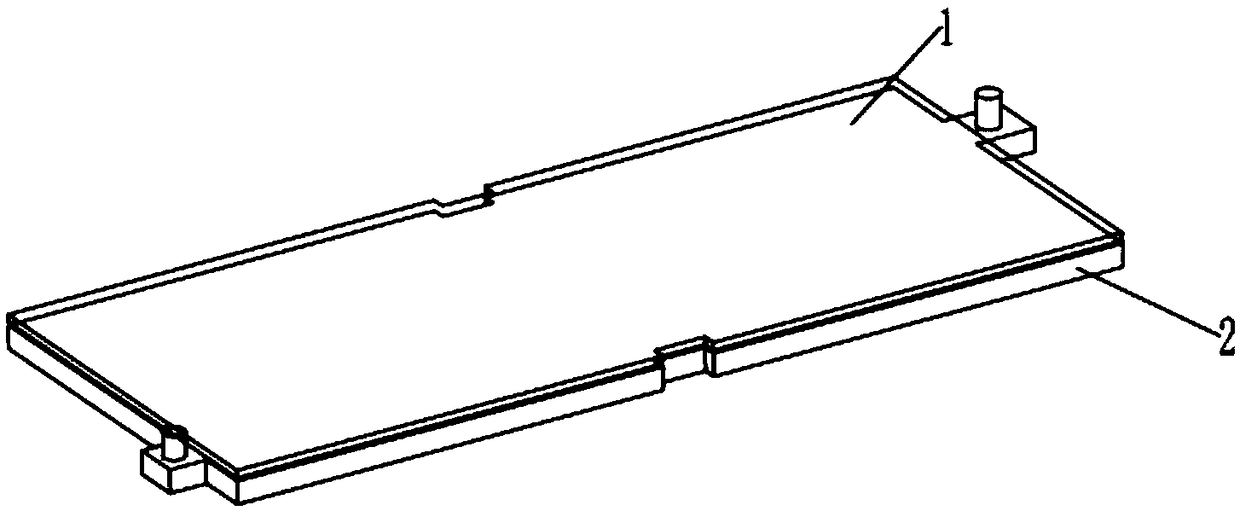
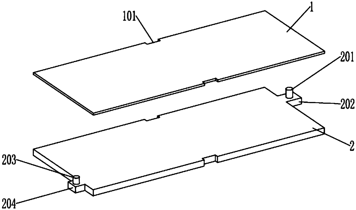
[0026] Such as Figure 1-5 As shown, a liquid cold plate with integrated heat conduction and heat insulation layer includes a liquid cold plate main body 2, the upper end surface of the liquid cold plate main body 2 is provided with a heat conduction layer 1, and the thickness of the heat conduction layer 1 is 0.1-10mm , the optimal thickness is 1-5mm, the heat conduction layer 1 is an adhesive, and the heat conduction layer 1 is made of heat conduction silica...


PUM

PropertyMeasurementUnit
thicknessaaaaaaaaaa
thicknessaaaaaaaaaa

Abstract

The invention discloses a liquid-cooled plate with integrated heat conductive layer, including a liquid-cooled plate body. The upper end surface of the liquid cooling plate main body is provided witha heat conductive layer, and the heat conductive layer is an adhesive, and the adhesive is bonded and solidified with the upper end surface of the liquid cooling plate main body; one end of the liquidcooling plate main body is provided with a liquid outlet plate; the liquid outlet plate is provided with a liquid outlet pipe; the other end of the liquid cooling plate main body is provided with a liquid inlet plate; and the liquid inlet plate is provided with a liquid inlet pipe. As that heat conduction layer is directly solidified and for on the surface of the water-cooled plate, the gap between the heat conduction gasket and the surface of the liquid-cooled plate is eliminated, the heat dissipation efficiency and the capability of the liquid-cooled plate are improved, and the process of the assembly plant is reduced, and the efficiency is improved; It can distribute the refrigerant evenly and ensure the heat dissipation effect of the liquid cooling plate body to be more uniform and reliable. On the one hand, it can increase the velocity and flow rate and improve the efficiency of heat dissipation; on the other hand, it can increase the area of heat dissipation and increase the heat exchange capacity of liquid per unit area.

Description

technical field [0001] The invention relates to the technical field of battery heat dissipation, in particular to a liquid cold plate with an integrated heat conduction layer. Background technique [0002] Electric vehicles are a kind of new energy vehicles, and now more and more people pay attention to them. In electric vehicles, the power battery is its core component. The charging and discharging efficiency of the power battery is directly related to the performance of the electric vehicle. Since the power battery is generally a mutual conversion of chemical energy and electrical energy, its charging and discharging efficiency is affected by temperature. [0003] The power battery will generate a lot of heat during the working process. If the heat cannot be dissipated quickly and effectively, the temperature of the power battery will increase. If the temperature rise exceeds its reasonable temperature range (such as 25 ~ 45 ℃) , It will reduce the efficiency and service ...

Claims


Application Information

Patent Timeline
Patent Type & Authority Applications(China)
IPC IPC(8): H01M10/613H01M10/617H01M10/625H01M10/6554H01M10/6567
CPCH01M10/613H01M10/617H01M10/625H01M10/6554H01M10/6567Y02E60/10
Inventor 宋春亮施浩威俞宁
Owner 浙江清优材料科技有限公司
Why Eureka
Try Eureka