
Multi-function UAV for power patrol inspection

An electric power inspection and unmanned aerial vehicle technology, applied in the field of unmanned aerial vehicles, can solve the problems of unreasonable structure setting of multi-rotor type unmanned aerial vehicles, damage or even reimbursement of internal electronic components, shortening the service life of unmanned aerial vehicles, etc. Reliable, power saving, simple structure

Inactive Publication Date: 2019-01-11
STATE GRID ZHEJIANG ELECTRIC POWER +2
View PDF4 Cites 3 Cited by
  • Summary
  • Abstract
  • Description
  • Claims
  • Application Information

AI Technical Summary

Problems solved by technology

There are many advantages in applying UAV technology to the field of power line inspection. However, due to the particularity and complexity of the tasks performed by multi-rotor UAVs, it is determined that it must carry a large number of sophisticated electronic equipment, and must be able to face For a variety of harsh and even extreme environments
However, there are still deficiencies in the existing UAV structure: the structure setting of the multi-rotor UAV is unreasonable, and the waterproof performance is poor. Once the water enters, the internal electronic components will be damaged or even reimbursed, thereby seriously shortening the use of the UAV. Life expectancy, complex structure, difficult assembly and disassembly operations, inconvenient maintenance, low battery storage capacity, drones generally can only fly for 0.5-1.5 hours at a time, coupled with other electrical equipment, faster power consumption, short working hours, Inconvenient to use, poor practicality

Method used


Image

  • Multi-function UAV for power patrol inspection
  • Multi-function UAV for power patrol inspection
  • Multi-function UAV for power patrol inspection

Examples


Embodiment Construction

[0023] In the description of this embodiment, it should be noted that if the terms "center", "upper", "lower", "left", "right", "vertical", "horizontal", "inner", " Outside", "front", "rear", etc., the orientation or positional relationship indicated is based on the orientation or positional relationship shown in the drawings, which is only for the convenience of describing the present invention and simplifying the description, rather than indicating or implying Any device or element must have a specific orientation, be constructed and operate in a specific orientation and, therefore, should not be construed as limiting the invention. In addition, the terms "first", "second", and "third" are used for descriptive purposes only, and should not be understood as indicating or implying relative importance.

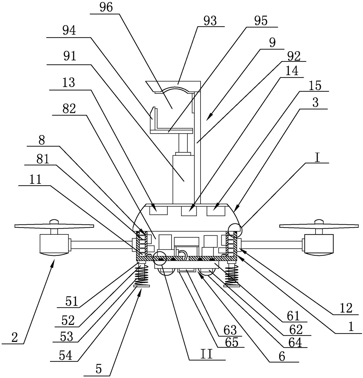
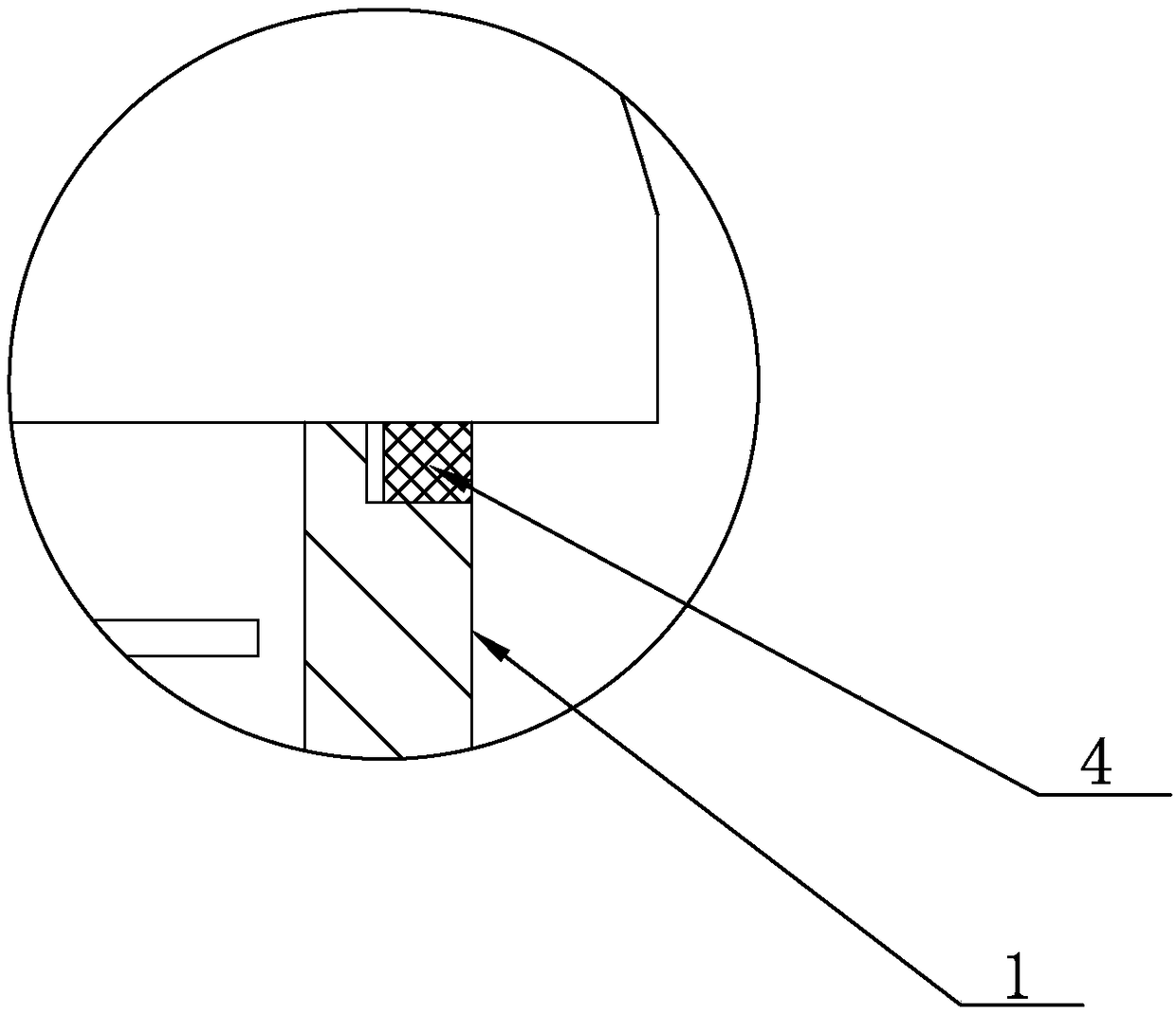
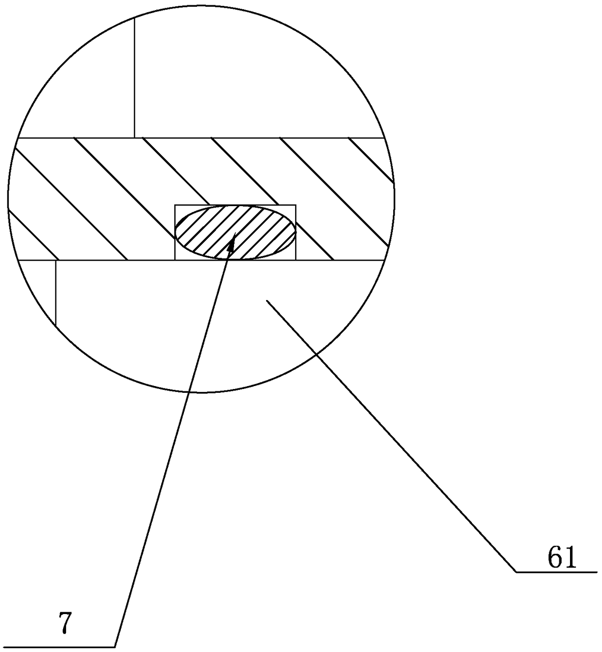
[0024] see figure 1 , figure 2 , image 3 and Figure 4, the multifunctional unmanned aerial vehicle suitable for electric power inspection disclosed by the present invent...


PUM


Abstract

The invention discloses a multifunctional unmanned aerial vehicle (UAV) suitable for electric power patrol inspection, which comprises a UAV main body, an object cavity is arranged in the UAV main body, and a plurality of rotor flying devices are arranged on the sides of the UAV main body. An upper end of that main body of the unmanned aerial vehicle is provided with a waterproof upper shell, anda first waterproof sealing ring is arranged between the waterproof upper shell and the main body of the unmanned aerial vehicle; an electronic component mounting cavity with an opening facing upward is arranged in the middle of the aluminum radiator in the housing cavity. The side surface of the waterproof upper shell is an arc surface, the upper end surface of the waterproof upper shell is a plane, the waterproof upper shell is made of transparent plastic material, the upper end surface of the waterproof upper shell is fixedly provided with an automatic cable grasping manipulator, and the waterproof upper shell is fixedly provided with a thermal infrared imager, a video camera and an ultrasonic flaw detector. The technical scheme has the advantages of reasonable structure design, simple structure, easy assembly and disassembly, good waterproofing performance, long working time, convenient use and normal operation under harsh conditions such as rainy day and night.

Description

technical field [0001] The invention relates to the technical field of unmanned aerial vehicles, in particular to a multifunctional unmanned aerial vehicle suitable for electric power inspection. Background technique [0002] UAV is an unmanned aircraft controlled by wireless remote control equipment and programs, and has been widely used in military and civilian fields. There are many types of drones, which are widely used in aerial photography, detection, search and rescue, security, resource exploration, agriculture, etc. Multi-rotor drones have low requirements for take-off and landing environments due to their simple and compact mechanical structure, more flexible actions, and It is easy to operate, and can realize take-off, hovering, and landing in a small atmosphere, and is particularly valued. There are many advantages in applying UAV technology to the field of power line inspection. However, due to the particularity and complexity of the tasks performed by multi-ro...

Claims


Application Information

Patent Timeline
Patent Type & Authority Applications(China)
IPC IPC(8): H02G1/02B64C39/02
CPCH02G1/02B64C39/02B64U50/19B64U10/10B64U2101/00
Inventor 陈蕾徐重酉潘杰锋高文婷袁忠君刘月娥王彦波曹华朱岩李峥嵘
Owner STATE GRID ZHEJIANG ELECTRIC POWER
Learn More