A motor shaft current eliminating structure and motor

A motor shaft and shaft current technology, which is applied in the direction of structural connection, electrical components, electromechanical devices, etc., can solve the problems of complex motor structure, large volume, and weakened shaft current elimination effect, and achieve a compact structure, low cost, and simple structure Effect

Pending Publication Date: 2019-01-11
GUANGZHOU XIAOPENG MOTORS TECH CO LTD
View PDF0 Cites 14 Cited by
  • Summary
  • Abstract
  • Description
  • Claims
  • Application Information

AI Technical Summary

Problems solved by technology

[0005] In order to solve the above-mentioned technical problems of complex structure, large volume and weakened shaft current elimination effect of the long-term use of the motor, the embodiment of the present invention proposes a motor shaft current elimination structure and a motor

Method used


Image

  • A motor shaft current eliminating structure and motor
  • A motor shaft current eliminating structure and motor

Examples


no. 1 example

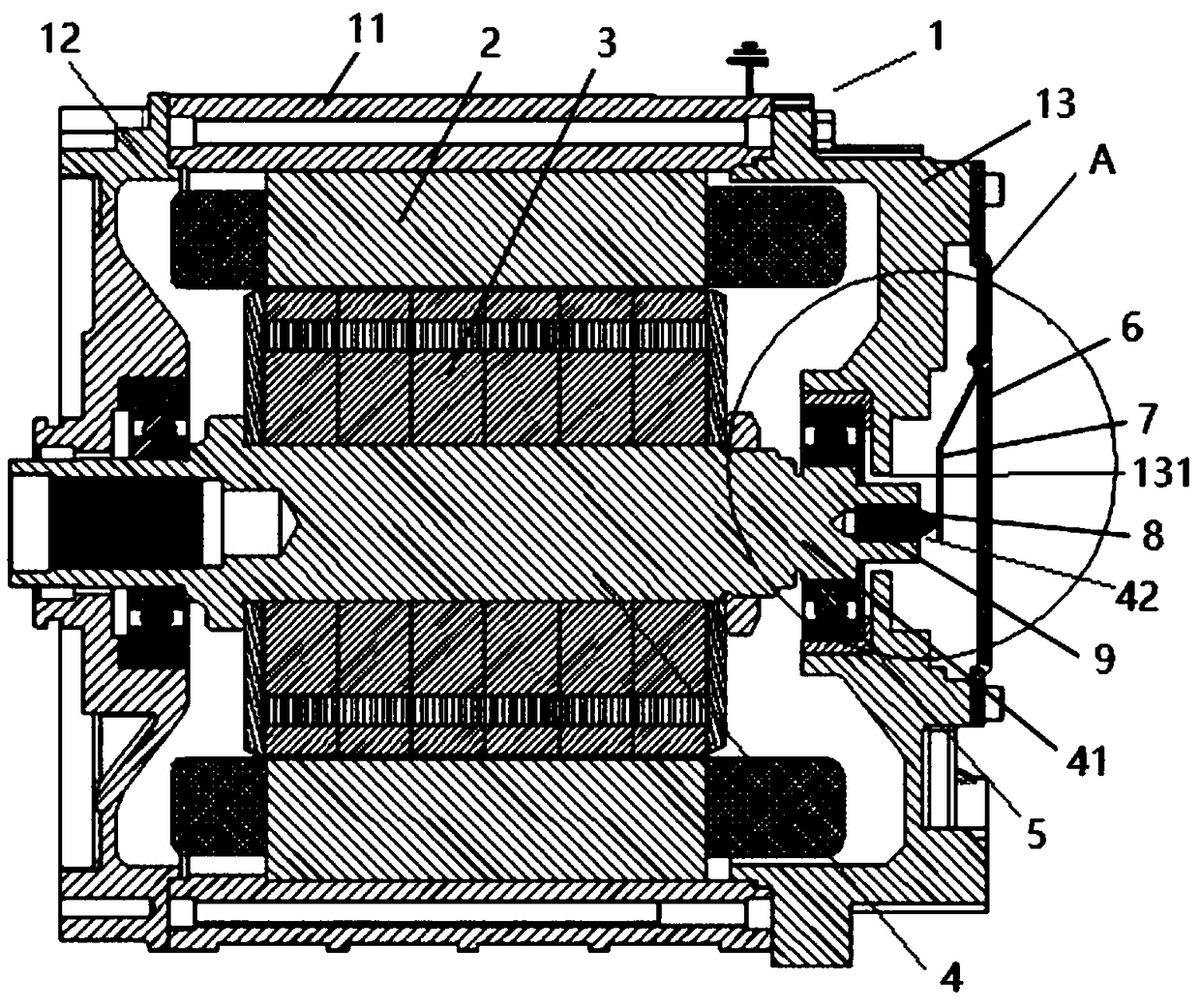
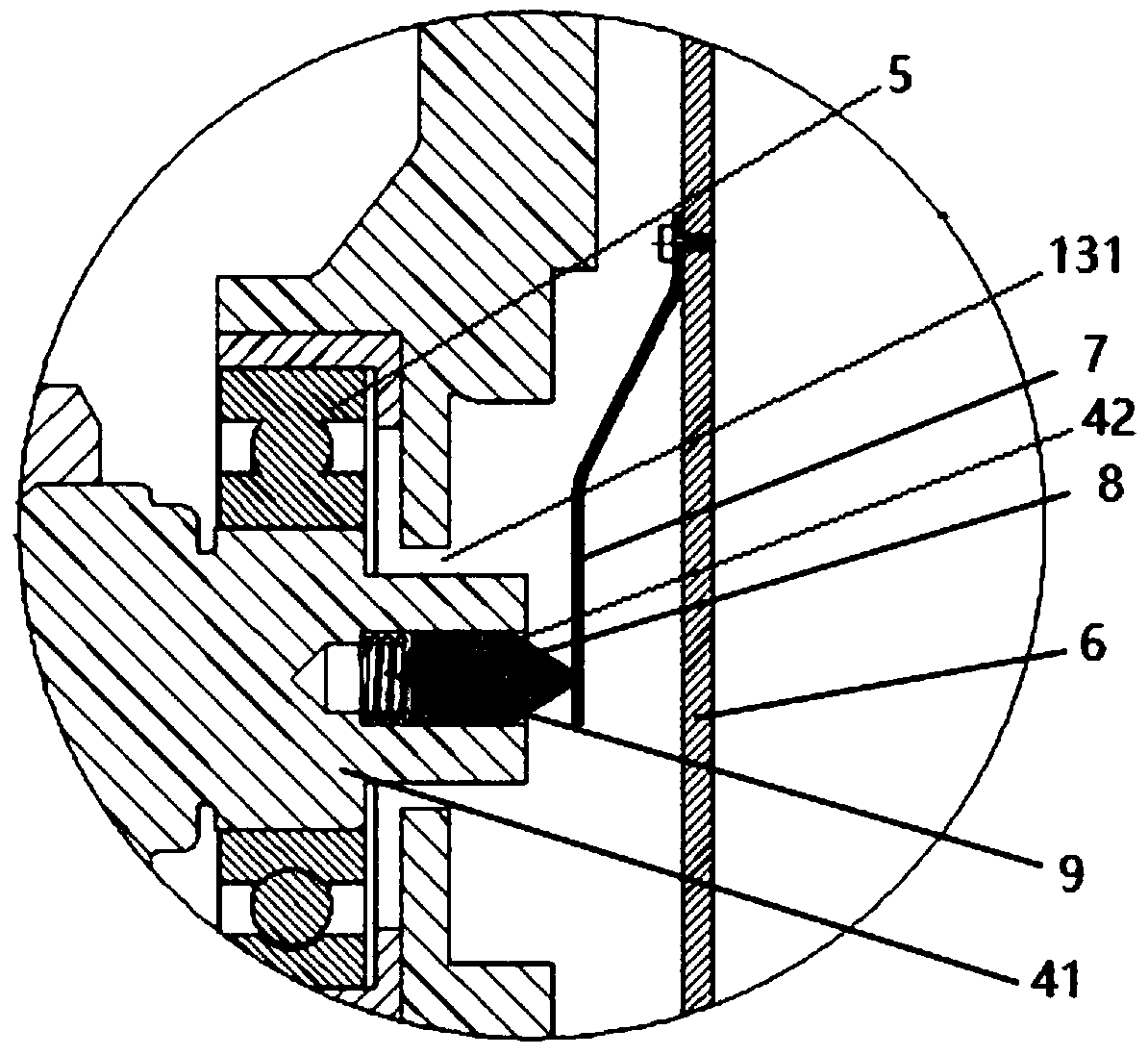
[0039] The shaft current eliminating structure A is arranged at the rear of the motor casing 1 , specifically on the outside of the rear end cover 13 of the motor casing 1 . The shaft current elimination structure A includes a back cover 6 , a conductive shrapnel 7 , a graphite rod 8 and a conductive spring 9 .

[0040] The rear cover 6 is electrically connected to the housing 1 of the motor. In this embodiment, the rear cover 6 is fixed on the rear end cover 13 of the housing 1 of the motor.

[0041] The conductive spring 9 and the graphite rod 8 are put into the graphite rod mounting hole 42 of the motor rotating shaft 4 in turn, one end of the conductive spring 9 is pressed against the graphite rod mounting hole 42, and the other end of the conductive spring 9 faces the graphite rod mounting hole 42 The outer side of the graphite rod 8 presses against the first end of the graphite rod 8, and the second end of the graphite rod 8 extends out of the graphite rod installation h...

no. 2 example

[0047] Compared with the first embodiment, the axial current elimination structure A in the second embodiment does not include the conductive spring 7, but includes the rear cover 6, the graphite rod 8 and the conductive spring 9 (not shown).

[0048] The rear cover 6 is electrically connected to the housing 1 of the motor. The conductive spring 9 and the graphite rod 8 are put into the graphite rod mounting hole 42 of the motor rotating shaft 4 in turn, one end of the conductive spring 9 is pressed against the graphite rod mounting hole 42, and the other end of the conductive spring 9 faces the graphite rod mounting hole 42 The outer side of the graphite rod 8 presses against the first end of the graphite rod 8 , and the second end of the graphite rod 8 extends out of the graphite rod installation hole 42 and is pressed against the inner side of the rear cover plate 6 .

[0049] Therefore, the shaft current conduction path formed by the shaft current elimination structure of ...

no. 3 example

[0053] Compared with the first embodiment, the axial current elimination structure A in the third embodiment does not include the conductive spring 9, but includes the rear cover plate 6, the graphite rod 8 and the conductive shrapnel 7 (not shown).

[0054] The rear cover 6 is electrically connected to the housing 1 of the motor.

[0055] The graphite rod 8 is put into the graphite rod mounting hole 42 of the motor shaft 4, the first end of the graphite rod 8 is pressed against the graphite rod mounting hole 42, and the second end of the graphite rod 8 stretches out of the graphite rod mounting hole 42.

[0056] The conductive elastic piece 7 is Z-shaped, and the first end of the conductive elastic piece 7 is electrically connected and fixed on the inner side of the rear cover 6, for example, by a screw, and the second end of the conductive elastic piece 7 is a free end, facing the graphite rod installation hole. The outer side of 42 presses against the second end of the gra...


PUM


Abstract

The invention relates to a motor shaft current eliminating structure and a motor. The motor shaft current eliminating structure comprises a rear cover plate, a graphite rod and at least one electrically conductive elastic member, the rear cover plate can be electrically connected to the housing of the motor. The graphite rod can be placed in a graphite rod mounting hole of a motor rotating shaft,and the conductive elastic member is an electrically conductive spring and / or an electrically conductive elastic piece; the graphite rod is electrically connected with the rear cover plate directly orthrough the electrically conductive elastic piece; and the graphite rod can be electrically connected with the motor rotating shaft directly or through the electrically conductive spring. The embodiment of the invention has the advantages of compact structure, simplicity and low cost. The graphite rod and the conductive elastic parts are all inside the motor, which are not affected by the external environment, and do not produce noise when running, so the conductive parts are reliable.

Description

technical field [0001] The invention belongs to the technical field of motors, and in particular relates to a motor shaft current elimination structure and a motor. Background technique [0002] With the rapid development of electric vehicle technology, higher requirements are put forward for the driving motor of electric vehicles. The motor generally generates shaft current, which is the current flowing through the motor shaft, bearings and casing. In the actual use of the motor, the shaft current will damage the bearing, which will lead to the formation of multiple parallel electro-corrosion lines on the raceway of the inner and outer rings of the bearing for a long time. At the same time, it will cause the motor to work loudly, and the temperature of the motor bearing will rise and cause premature failure. [0003] The reasons for the shaft current generated by the drive motor of an electric vehicle mainly include: 1) the asymmetry of the magnetic circuit and the circuit...

Claims


Application Information

Patent Timeline
Patent Type & Authority Applications(China)
IPC IPC(8): H02K11/00H02K5/22
CPCH02K11/0094H02K5/22
Inventor 吴发亮孔庆波齐洪刚
Owner GUANGZHOU XIAOPENG MOTORS TECH CO LTD
Why Eureka
Try Eureka