A method for fault-tolerant control of brushless DC motor

A brush DC motor, fault-tolerant control technology, applied in the direction of motor control, control system, motor parameter estimation/correction, etc., can solve the problems of obtaining the commutation position of the rotor, unable to use fault discrete Hall signals, etc., to achieve high precision Effect of commutation point position

Active Publication Date: 2019-01-11
CHANGZHOU BAOLONG MOTORS
View PDF10 Cites 13 Cited by
  • Summary
  • Abstract
  • Description
  • Claims
  • Application Information

AI Technical Summary

Problems solved by technology

[0003] The purpose of the present invention is to solve the problem that the rotor commutation position cannot be obtained by using the fault discrete Hall sig

Method used


Image

  • A method for fault-tolerant control of brushless DC motor
  • A method for fault-tolerant control of brushless DC motor
  • A method for fault-tolerant control of brushless DC motor

Examples


Embodiment Construction

[0050] In order to make the object, technical solution and advantages of the present invention clearer, the present invention will be further described in detail below in conjunction with the accompanying drawings. It should be understood that the specific embodiments described here are only used to explain the present invention, not to limit the present invention.

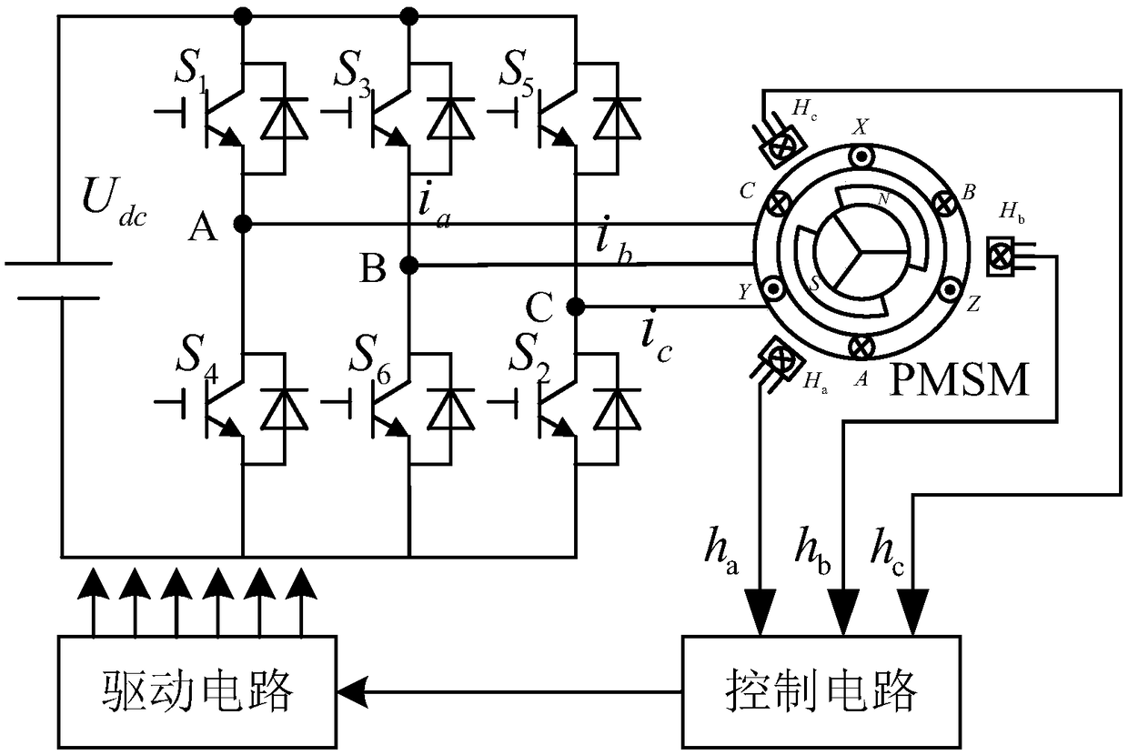
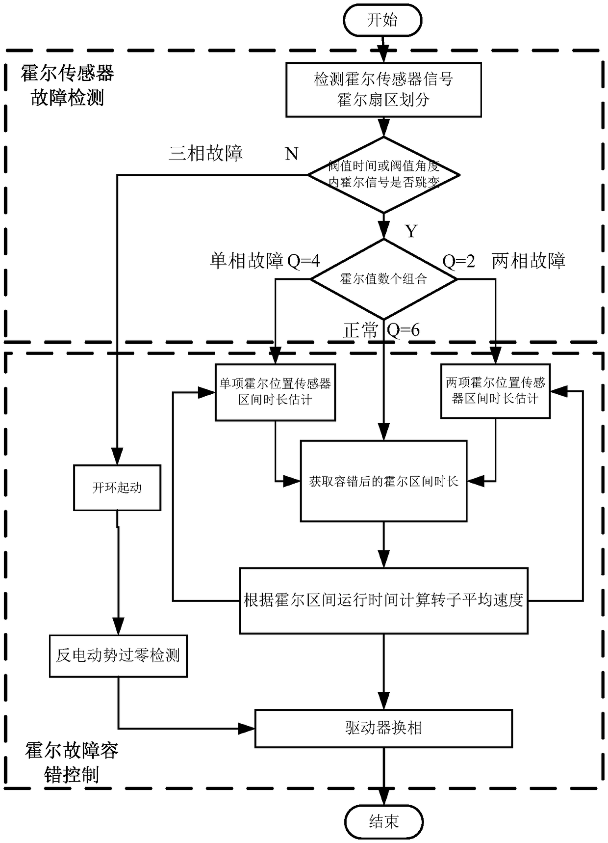
[0051] Such as figure 1 As shown, the present invention provides a brushless DC motor fault-tolerant control method under the brushless DC control system, such as figure 2As shown, the fault-tolerant control method of the brushless DC motor includes the following steps:

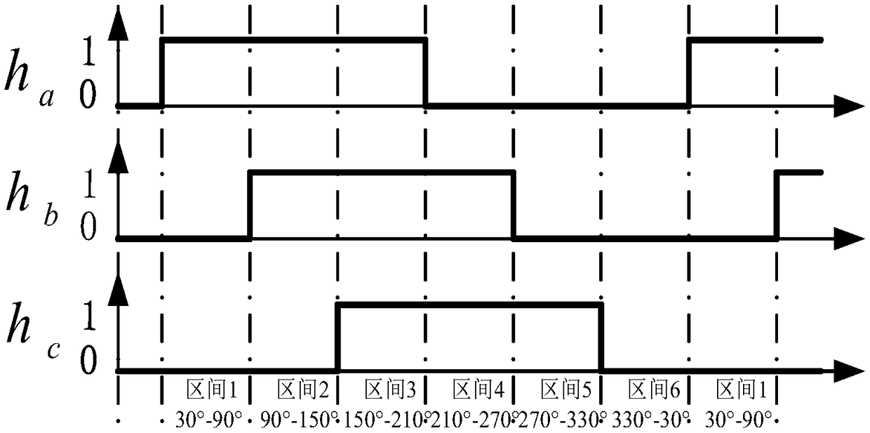
[0052] Step 1: Install three switch-type Hall position sensors symmetrically in the center of the outer circumference of the brushless DC motor rotor. During the operation of the motor, the three-way Hall signals with a phase difference of 60° are obtained through the Hall position sensor, such as image 3 shown;

[0053] Step 2: According t...


PUM


Abstract

A method for fault-tolerant control of brushless DC motor feature that that output of Hall sensor is monitored in real time during the operation of motor, and the Hall value of output of Hall elementis used to judge the fault of single-phase, two-phase and three-phase Hall element. Wh three-phase fault occurs, directly through the traditional three-stage start from zero speed to the motor closed-loop state, through the back-EMF zero-crossing detection method to detect the rotor position and speed, the normal operation of the motor is achieved. When the single-phase and two-phase Hall elementsfail, the motor speed is calculated by the average speed algorithm and the commutation time of the driving circuit is estimated according to the speed. This method can effectively solve the problem that the motor can not run normally due to the fault of Hall position sensor.

Description

technical field [0001] The invention belongs to the field of brushless direct current motor control, relates to a brushless direct current motor, in particular to a fault-tolerant control method of a brushless direct current motor. Background technique [0002] In a high-performance brushless DC motor control system, in order to accurately obtain the rotor speed and position information required for the closed-loop speed, it is generally necessary to install a high-precision position sensor on the shaft end of the motor rotor, although the introduction of a high-precision position sensor can ensure the motor. Control results, but there are also a series of problems such as reduced system reliability and increased control costs. In order to solve the above problems, the Hall position sensor is selected to complete the estimation of the speed and position, but the harsh environment, severe vibration and other conditions will cause the Hall sensor to fail, and the rotor positio...

Claims


Application Information

Patent Timeline
IPC IPC(8): H02P6/16H02P23/14H02P29/028
CPCH02P6/16H02P23/14H02P29/028H02P29/032H02P2203/03
Inventor 朱文章杨路魏海峰
Owner CHANGZHOU BAOLONG MOTORS
Why Eureka
Try Eureka