
A medical bone drill with multiple functions

A multi-functional, bone drill technology, applied in the field of medical devices, can solve problems such as troubles, and achieve the effects of reducing working current, prolonging use time, and sufficient power

Pending Publication Date: 2019-01-15
上海博进医疗器械有限公司
View PDF0 Cites 2 Cited by
  • Summary
  • Abstract
  • Description
  • Claims
  • Application Information

AI Technical Summary

Problems solved by technology

[0002] In orthopedic clinical operations, bone drills are commonly used in operations such as craniotomy and drilling. Since different operations require bone drills with different speeds and torques, doctors need to prepare multiple sets of bone drills during clinical operations. In order to prepare for various applications, causing unnecessary trouble

Method used


Image

  • A medical bone drill with multiple functions
  • A medical bone drill with multiple functions
  • A medical bone drill with multiple functions

Examples


no. 2 example

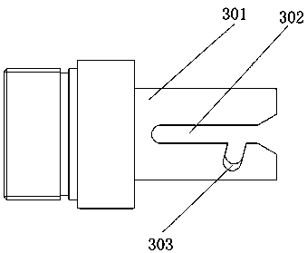
[0051] Such as Figure 5 As shown, the difference from the first embodiment is a multifunctional medical bone drill provided in this embodiment. The drill bit 401 used includes a drill chuck 403 and an output shaft 501. Both ends of the output shaft 501 are connected to the drill chuck 403. The connecting spindle 402 is connected. One end of the connecting spindle 402 is partially inserted into the output shaft 501. The outer periphery of the connecting spindle 402 that penetrates the output shaft 501 is covered with a gasket 502. The other end of the connecting spindle 402 penetrates the tail sleeve 301 and connects Slot 106 connection;

[0052] The outer sleeve of the output shaft 501 is provided with a front sleeve 503 connected to the tail sleeve 301, the end of the tail sleeve 301 away from the positioning groove is connected to the front sleeve 503, and the end of the front sleeve 503 away from the tail sleeve 301 is connected with a second front cover 504 , A sign ring is ...

no. 3 example

[0056] Such as Image 6 As shown, the difference from the first embodiment is that the multifunctional medical bone drill provided in this embodiment uses a drill 401 that includes a housing 601, a pressure rod 602, and a locking member, and the locking member includes a locking sleeve 603 And the locking chuck 604 and the locking wheel 605 are arranged inside the locking sleeve 603, the housing 601 is sleeved on the locking sleeve 603, and the locking chuck 604 and the locking wheel 605 are provided at the same end of the locking sleeve 603 , The locking chuck 604 is arranged on the inner wall of the locking sleeve 603, the inner wall of the locking chuck 604 is provided with three consistent locking wheels 605, the other end of the locking sleeve 603 is partially inserted into the connecting spindle 402, and the connecting spindle 402 The end away from the locking sleeve 603 is connected to the connecting groove 106, the tail sleeve 301 is sleeved on the connecting spindle 40...


PUM


Abstract

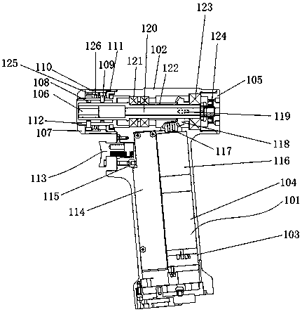
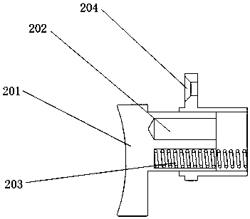
A medical bone drill with multiple functions includes a connected bone drill body and a drill bit, a bone drill body includes a control device, chassis, handle, Motor, transmission, the handle is fixedly connected to the bottom of the chassis, the transmission device is arranged inside the chassis, the motor is arranged inside the handle. The top of the motor is provided with a gear set connectedwith the transmission device, one end of the transmission device near the gear set is provided with a back splicing cap connected with the casing, the other end is provided with a connecting groove connected with the drill bit, the drill bit is provided with a connecting spindle matched with the connecting groove, the connecting spindle is sleeved with a tail sleeve connected with the casing, andthe casing is provided with a locking device connected with the tail sleeve. The locking device comprises an inner sleeve splicing cap, a positioning pin, a knob and a shell splicing cap, wherein theknob is sleeved on the transmission device; an inner sleeve is arranged between the knob and the transmission device; the inner sleeve is respectively connected with the inner sleeve splicing cap andthe shell; the shell splicing cap is sleeved on one end of the inner sleeve near the shell; the positioning pin is connected with the inner sleeve; and a positioning groove matching with the positioning pin is arranged on the tail sleeve.

Description

Technical field [0001] The invention relates to the technical field of medical devices, in particular to a multifunctional medical bone drill. Background technique [0002] In orthopedic clinical operations, bone drills are commonly used instruments in craniotomy and drilling operations. Since different operations require bone drills with different rotation speeds and different torques, doctors need to prepare multiple sets of bone drills during clinical operations. To prepare for various applications, causing unnecessary trouble. Summary of the invention [0003] The technical problem to be solved by the present invention is to provide a multifunctional medical bone drill, which can reduce the diameter of the motor output shaft, effectively solve the contradiction between small volume and large torque output; use an oil seal as a dynamic sealing structure, increase an effective sealing structure, and can It prevents blood water from entering the bone drill body and will not ca...

Claims


Application Information

Patent Timeline
Patent Type & Authority Applications(China)
IPC IPC(8): A61B17/16
CPCA61B17/1615A61B17/1695
Inventor 王浩王熙迥曲人晶
Owner 上海博进医疗器械有限公司
Learn More