Assembly-type shear wall connecting structure and construction method thereof

A technology for connecting structures and shear walls, applied to walls, building components, building structures, etc., can solve the problems of difficult accurate alignment of steel ends, troublesome refilling of concrete, low construction efficiency, etc., and achieve simple and ingenious structure. Improve construction efficiency and reliable connection

Active Publication Date: 2019-01-15
HEILONGJIANG COLLEGE OF CONSTR
View PDF8 Cites 5 Cited by
  • Summary
  • Abstract
  • Description
  • Claims
  • Application Information

AI Technical Summary

Problems solved by technology

[0003] The connection method of the horizontal joints of prefabricated shear walls in prefabricated buildings is generally to reserve the ends of the steel bars, and then use the grouting sleeve to connect and fix the ends of the stee

Method used


Image

  • Assembly-type shear wall connecting structure and construction method thereof
  • Assembly-type shear wall connecting structure and construction method thereof
  • Assembly-type shear wall connecting structure and construction method thereof

Examples


specific Embodiment approach 1

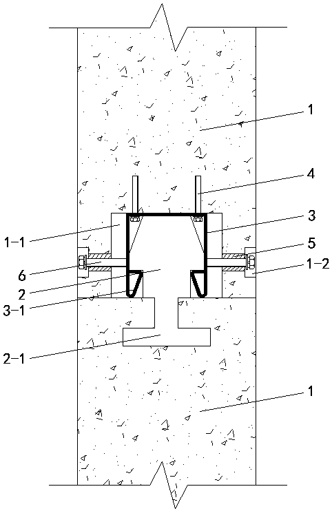
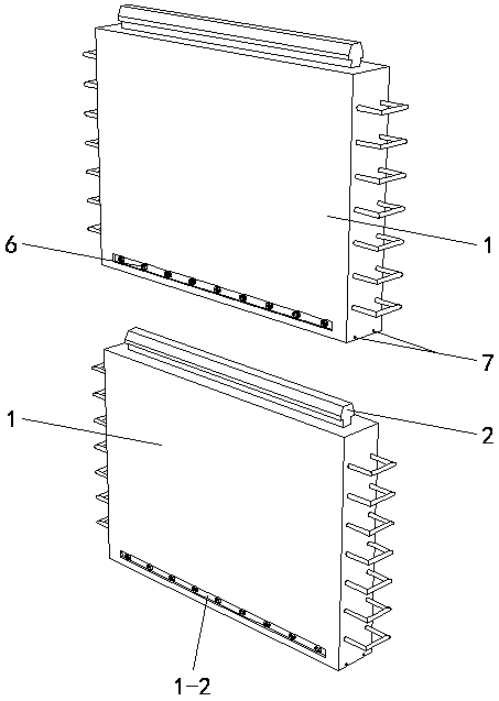
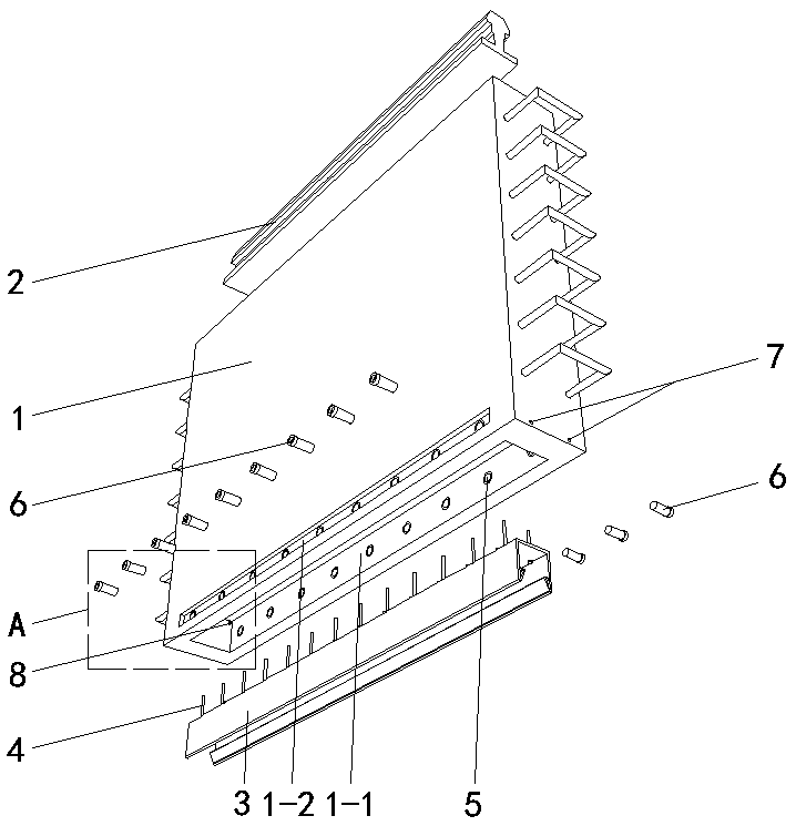
[0018] Specific implementation mode one: as Figure 1~Figure 5 As shown, the present invention discloses a prefabricated shear wall connection structure, including a plurality of shear wall monomers 1, and inserting steel parts 2 and positioning channel steels between each two shear wall monomers 1 3 connected into one body, the middle position of the upper end surface of each shear wall unit 1 is buried and fixed along its length direction with a plug-in steel part 2, and the plug-in steel part 2 is strip steel and includes an inverted T-shaped pre- The buried bottom 2-1 and the wedge-shaped exposed top 2-2, and the two sides of the wedge-shaped exposed top 2-2 are respectively provided with clamping parts 2-3, and the middle position of the lower end surface of each shear wall unit 1 is along its length direction A rectangular slot 1-1 is concavely provided, and the rectangular slot 1-1 corresponds to the inserted steel part 2 and its width is greater than the width of the i...

specific Embodiment approach 2

[0019] Specific implementation mode two: as figure 1 , 4 As shown, this embodiment is a further description of specific embodiment 1. A groove is horizontally provided on the outer sides of the groove walls on both sides of the rectangular slot 1-1 of each shear wall unit 1 in the length direction. Groove 1-2, said groove 1-2 connects a plurality of corresponding inner threaded sleeves 5, and the outer end of each said inner threaded sleeve 5 is flush with the groove bottom of corresponding groove 1-2. After the two support arms of the positioning channel steel 3 are defined by the fastening bolts 6, the shear wall monomer 1 is smoothed with mortar in the groove 1-2.

specific Embodiment approach 3

[0020] Specific implementation mode three: as figure 1 As shown, this embodiment is a further description of specific embodiment one. The width of the clip joint 3-1 of the positioning channel steel 3 is smaller than the two arms of the positioning channel steel 3 and the length direction of the rectangular slot 1-1. Spacing between side channel walls.


PUM

PropertyMeasurementUnit
Thicknessaaaaaaaaaa

Abstract

An assembly-type shear wall connecting structure and a construction method thereof relate to a wall connecting structure and a construction method thereof. The upper end surface of the shear wall is embedded and fixed with an insertion connecting steel piece, the insertion connecting steel piece is provided with a snap portion, and the lower end surface of the shear wall is concavely provided witha rectangular insertion slot. The two sides of the bottom of a positioning steel channel are connected and fixed with the bottom of the rectangular insertion slot by two rows of positioning bolts. Clamping heads are arranged on the free ends of two supporting arms of the positioning steel channel in a bending manner, and the insertion connecting steel piece matches with the positioning steel channel. The snap portion and the clamping heads are in clamping cooperation to prevent disconnection of the insertion connecting steel piece and the positioning steel channel. A plurality of internally threaded sleeves are respectively embedded in the groove walls on both sides of the rectangular insertion slot in the longitudinal direction, and internal thread sleeves are screwed with fastening bolts to support and limit the two supporting arms of the positioning channel steel. One side of the slot walls of the rectangular insertion slot in the width direction is provided with two grouting holes, and the other side of the slot walls is provided with two discharging holes. The assembly is simple and effective, the alignment is accurate and fast, and certain support and positioning effects areprovided.

Description

technical field [0001] The invention relates to a wall connection structure and a construction method thereof, in particular to an assembled shear wall connection structure and a construction method thereof. Background technique [0002] The prefabricated building is a building form in which a large number of building parts are processed and prefabricated in the factory, and then transported to the construction site for assembly. Compared with the traditional cast-in-place concrete building form, it has many advantages such as energy saving and environmental protection, improving operating efficiency, and saving materials. It is also the main development direction of the construction industry. [0003] The connection method of the horizontal joints of prefabricated shear walls in prefabricated buildings is generally to reserve the ends of the steel bars, and then use the grouting sleeve to connect and fix the ends of the steel bars during assembly. The connection method has...

Claims


Application Information

Patent Timeline
IPC IPC(8): E04B2/56
CPCE04B2/56
Inventor 徐晓娜李楠信思源张琨沈义叶飞王作成吴士超富小蔓崔永红
Owner HEILONGJIANG COLLEGE OF CONSTR
Why Eureka
Try Eureka