Magnetic levitation air compressor
An air compressor and magnetic levitation technology, applied in liquid variable capacity machinery, mechanical equipment, variable capacity pump components, etc., can solve the problems of compressed air noise pollution, difficulty in improving blast efficiency, etc., to reduce wear and improve compression. The effect of efficiency
- Summary
- Abstract
- Description
- Claims
- Application Information
AI Technical Summary
Problems solved by technology
Method used
Image
Examples
Embodiment 1
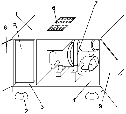
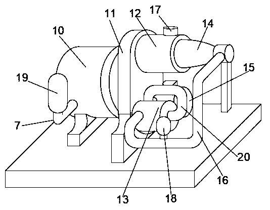
[0027] Embodiment 1: refer to Figure 1-2 ;
[0028] A magnetic levitation air compressor, including a fan housing 1 and support feet 2, the lower surface of the fan housing 1 is fixedly connected with the support feet 2, and the inside of the fan housing 1 is provided with a frequency conversion chamber 3 and a fan system chamber 4. A frequency converter 5 is fixedly installed in the frequency conversion chamber 3, a cooling device 6 and a blower system 7 are fixedly installed in the fan system chamber 4, a control box door 8 is installed on the front opening of the frequency conversion chamber 3, and a useful In order to control and adjust the control panel of the frequency converter 5, the cooling device 6 and the blast system 7, the front opening of the fan system chamber 4 is provided with a system box door 9 for quick maintenance and opening; the blast system 7 includes a drive box 10, and the drive box The outer surface of 10 is provided with a liquid cooler 19 for the...
Embodiment 2
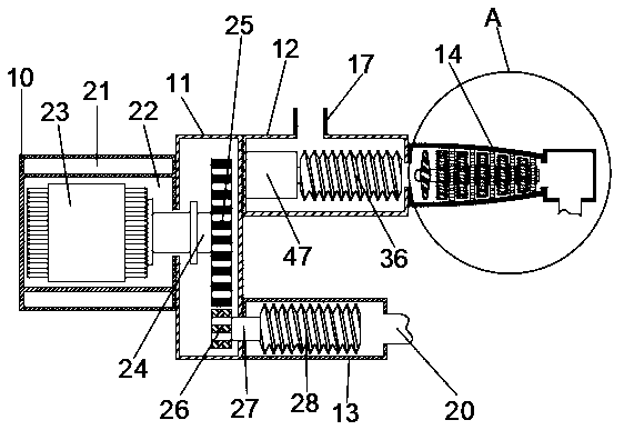
[0030] Embodiment 2: refer to Figure 3-6 , the basis of the embodiment 1 is different in that;
[0031] The inside of the drive box 10 is provided with a liquid chamber 21 and a motor chamber 22 for cooling fluid flow, the liquid chamber 21 communicates with the liquid cooler 19, a permanent magnet synchronous motor 23 is fixedly installed in the motor chamber 22, and the permanent magnet synchronous motor 23 ends are fixed Connected with a rotating shaft 24, the rotating shaft 24 extends into the gear box 11 and is fixedly connected with the end face of the rotating gear 25, and the rims on both sides of the lower part of the rotating gear 25 are meshed with the driven gear 26 rims respectively.
[0032] Both the primary compression tank 13 and the secondary compression tank 15 are provided with active screw rods 28 inside. The active screw rods 28 are movably connected to the outer surface of the driven screw rod 32. The left end of the active screw rod 28 is fixedly connec...
Embodiment 3
[0037] Embodiment 3: refer to Figure 6 , the basis of the embodiment 1 is different in that;
[0038] The inside of the compression cylinder 14 is provided with moving vanes 45 and stationary vanes 41 at equidistant intervals, the outer end of the stationary vanes 41 is fixedly connected to the inner wall of the compression cylinder 14, the inner end of the stationary vanes 41 is fixedly connected to the outer surface of the positioning sleeve 42, and the middle of the positioning sleeve 42 Rotately connected with the outer surface of the supporting shaft 43, the inner end of the movable blade 45 is fixedly connected with the outer surface of the supporting shaft 43, the left end of the supporting shaft 43 is fixedly connected with the end surface of the rotating impeller 44, and the right end of the pressure cylinder 14 is provided with an air chamber 46, the air chamber 46 communicates with the first communication pipe 16 .
[0039] When the air flow enters the compression...
PUM
 Abstract
Description
Claims
Application Information
 - R&D
- Intellectual Property
- Life Sciences
- Materials
- Tech Scout
- Unparalleled Data Quality
- Higher Quality Content
- 60% Fewer Hallucinations
Browse by: Latest US Patents, China's latest patents, Technical Efficacy Thesaurus, Application Domain, Technology Topic, Popular Technical Reports.
© 2025 PatSnap. All rights reserved.Legal|Privacy policy|Modern Slavery Act Transparency Statement|Sitemap|About US| Contact US: help@patsnap.com


