A magnetic levitation air compressor

An air compressor and magnetic levitation technology, which is applied in the field of air compressors, can solve the problems of difficulty in improving blast efficiency and noise pollution of compressed air, and achieve the effects of reducing wear and improving compression efficiency.

Active Publication Date: 2019-08-09
LINAN PAIQI AIR PURIFYING TECH CO LTD
View PDF6 Cites 0 Cited by
  • Summary
  • Abstract
  • Description
  • Claims
  • Application Information

AI Technical Summary

Problems solved by technology

[0003] The purpose of the present invention is to solve the noise pollution when producing compressed air and at the same time it is difficult to improve the blowing efficiency and propose a magnetic levitation air compressor

Method used


Image

  • A magnetic levitation air compressor
  • A magnetic levitation air compressor
  • A magnetic levitation air compressor

Examples


Embodiment 1

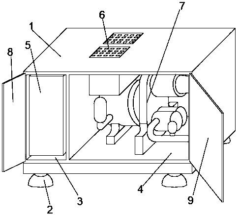
[0027] Embodiment 1: refer to Figure 1-2 ;

[0028] A magnetic levitation air compressor, including a fan housing 1 and support feet 2, the lower surface of the fan housing 1 is fixedly connected with the support feet 2, and the inside of the fan housing 1 is provided with a frequency conversion chamber 3 and a fan system chamber 4. A frequency converter 5 is fixedly installed in the frequency conversion chamber 3, a cooling device 6 and a blower system 7 are fixedly installed in the fan system chamber 4, a control box door 8 is installed on the front opening of the frequency conversion chamber 3, and a useful In order to control and adjust the control panel of the frequency converter 5, the cooling device 6 and the blast system 7, the front opening of the fan system chamber 4 is provided with a system box door 9 for quick maintenance and opening; the blast system 7 includes a drive box 10, and the drive box The outer surface of 10 is provided with a liquid cooler 19 for the...

Embodiment 2

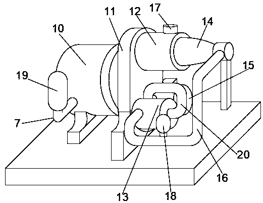
[0030] Embodiment 2: refer to Figure 3-6 , the basis of the embodiment 1 is different in that;

[0031] The inside of the drive box 10 is provided with a liquid chamber 21 and a motor chamber 22 for cooling fluid flow, the liquid chamber 21 communicates with the liquid cooler 19, a permanent magnet synchronous motor 23 is fixedly installed in the motor chamber 22, and the permanent magnet synchronous motor 23 ends are fixed Connected with a rotating shaft 24, the rotating shaft 24 extends into the gear box 11 and is fixedly connected with the end face of the rotating gear 25, and the rims on both sides of the lower part of the rotating gear 25 are meshed with the driven gear 26 rims respectively.

[0032] Both the primary compression tank 13 and the secondary compression tank 15 are provided with active screw rods 28 inside. The active screw rod 28 is movably connected to the outer surface of the driven screw rod 29. The left end of the active screw rod 28 is fixedly connecte...

Embodiment 3

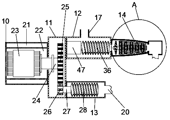
[0037] Embodiment 3: refer to Image 6 , the basis of the embodiment 1 is different in that;

[0038] The inside of the compression cylinder 14 is provided with moving vanes 45 and stationary vanes 41 at equidistant intervals, the outer end of the stationary vanes 41 is fixedly connected to the inner wall of the compression cylinder 14, the inner end of the stationary vanes 41 is fixedly connected to the outer surface of the positioning sleeve 42, and the middle of the positioning sleeve 42 Rotately connected with the outer surface of the support shaft 43, the inner end of the movable blade 45 is fixedly connected with the outer surface of the support shaft 43, the left end of the support shaft 43 is fixedly connected with the end surface of the rotating impeller 44, and the right end of the pressure cylinder 14 is provided with an air chamber 46, the air chamber 46 communicates with the first communication pipe 16 .

[0039] When the air flow enters the compression cylinder ...


PUM


Abstract

The invention discloses a magnetic levitation air compressor, and belongs to the field of air compressors. The magnetic levitation air compressor comprises a fan shell and support legs, wherein the periphery of the lower surface of the fan shell is fixedly connected with the support legs; a frequency conversion cavity and a fan system cavity are arranged inside the fan shell; a frequency converteris fixedly arranged in the frequency conversion cavity; a heat-dissipation device and a blowing system are fixedly arranged in the fan system cavity; a control box door is arranged at an opening in the front side of the frequency conversion cavity; the front side of the control box door is provided with a regulating and controlling panel for controlling and regulating the frequency converter, theheat-dissipation device and the blowing system; a system box door which can be opened and closed conveniently for rapid overhauling is arranged at the opening in the front side of the fan system cavity. By adopting the magnetic levitation air compressor, multi-stage air compression is designed, and boosting of compressed air is improved further through an air cylinder, so that the producing efficiency of the compressed air is improved effectively. Meanwhile, magnetic levitation support rotation centrifugal compression is adopted, so that noise pollution is lowered, the service life is prolonged, and the fan production efficiency is improved.

Description

technical field [0001] The invention relates to the field of air compressors, in particular to a magnetic levitation air compressor. Background technique [0002] An air compressor is a device used to compress gas. Air compressors are similar in construction to water pumps. Most air compressors are reciprocating piston, rotary vane or rotary screw. Centrifugal compressors are very large applications. There are many types of air compressors, such as: Roots blower, multi-stage centrifugal blower, single-stage centrifugal blower, etc. Such air compressors have defects in varying degrees. During the operation of the Roots blower, the vibration is large and the noise is polluted. Serious, long-term operation, low efficiency, multi-stage centrifugal blower, the compression efficiency gradually decreases with the increase of levels, single-stage centrifugal blower structure is simple but easy to damage, and low efficiency is not conducive to large-area use. Contents of the inv...

Claims


Application Information

Patent Timeline
Patent Type & Authority Patents(China)
IPC IPC(8): F04B41/06F04B39/06F04B39/00
CPCF04B39/00F04B39/0027F04B39/06F04B41/06
Inventor 韩大磊
Owner LINAN PAIQI AIR PURIFYING TECH CO LTD
Why Eureka
Try Eureka