
Storage tank for a cryogenic medium

A low-temperature medium, storage box technology, applied in gas treatment/storage effect, gas treatment/storage purpose, gas/liquid distribution and storage, etc., can solve problems such as bubble formation, pressure difference balance state interference, etc.

Inactive Publication Date: 2019-01-15
ROBERT BOSCH GMBH
View PDF7 Cites 4 Cited by
  • Summary
  • Abstract
  • Description
  • Claims
  • Application Information

AI Technical Summary

Problems solved by technology

If this gaseous leakage quantity is led back into the storage tank, disturbances to the equilibrium state existing in the storage tank may occur due to pressure and temperature differences
In addition, air bubbles may form when the gaseous leakage is introduced back into the storage tank, so that there is a risk that the gas bubble / liquid gas mixture is extracted from the storage tank

Method used


Image

  • Storage tank for a cryogenic medium
  • Storage tank for a cryogenic medium
  • Storage tank for a cryogenic medium

Examples


Embodiment Construction

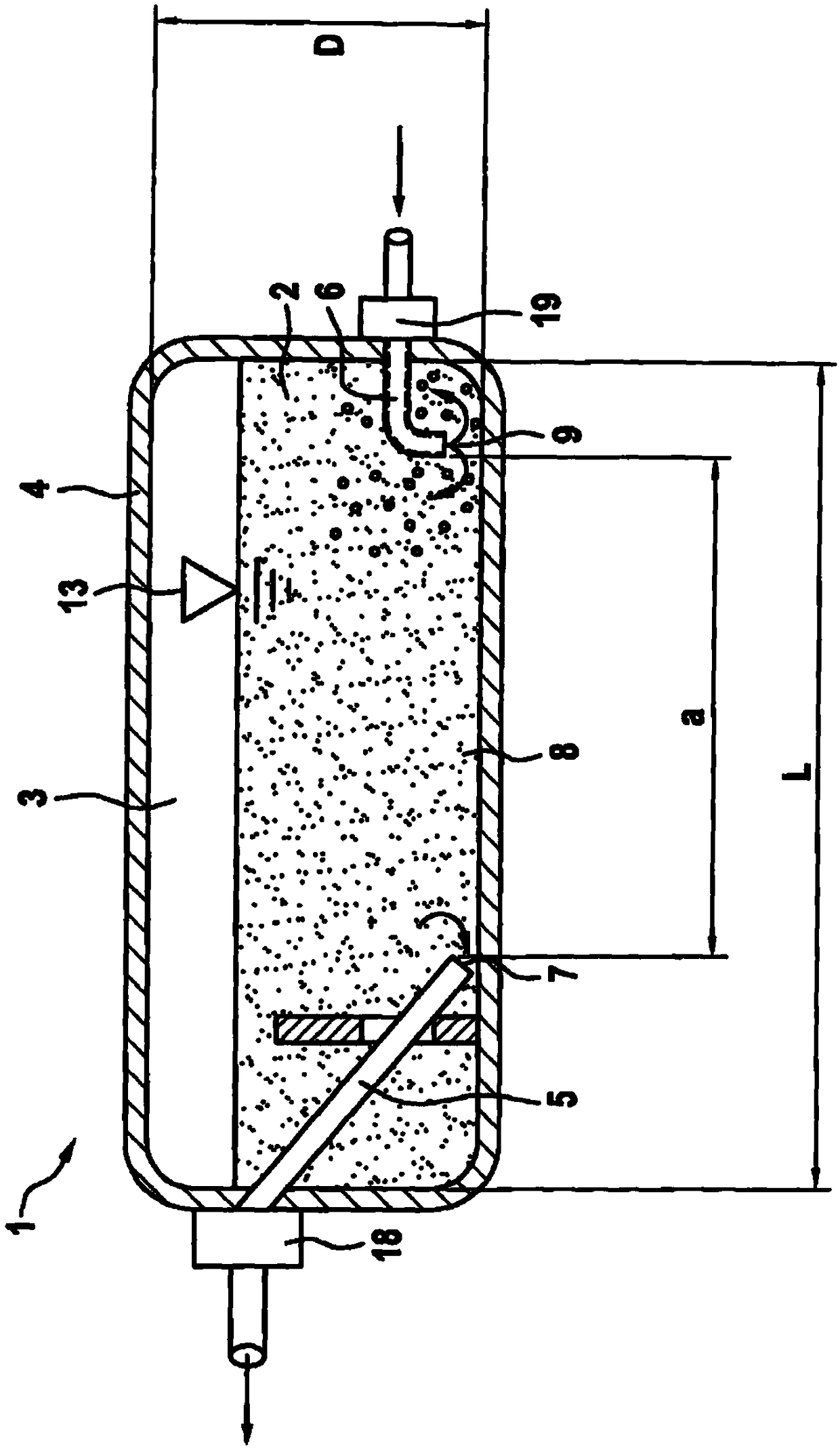
[0031] exist figure 1 The storage tank 1 shown in is used to store cryogenic medium 2 . In this case, in particular liquefied natural gas (LNG) may be involved. The medium 2 is accommodated in a tank interior 3 , which is delimited by a tank wall 4 . The tank interior 3 or the storage tank 1 has the shape of an elongated cylinder, which is defined by a length L and a diameter D. As shown in FIG. Storage box 1 is rounded on opposite end sides. Furthermore, on each end side a line 5 , 6 leads through the tank wall 4 into the tank interior 3 .

[0032] The first line 5 forms an extraction point 7 in the bottom region 8 of the tank interior 3 . The liquid medium 2 stored in the storage tank 1 is sucked in by means of a pump 18 connected to the line 5 and arranged on the outside of the storage tank 1 . The second line 6 serves to conduct the gaseous leakage quantity back into the storage tank 1 , wherein the second line 6 defines an insufflation point 9 . Since the blow-in po...


PUM


Abstract

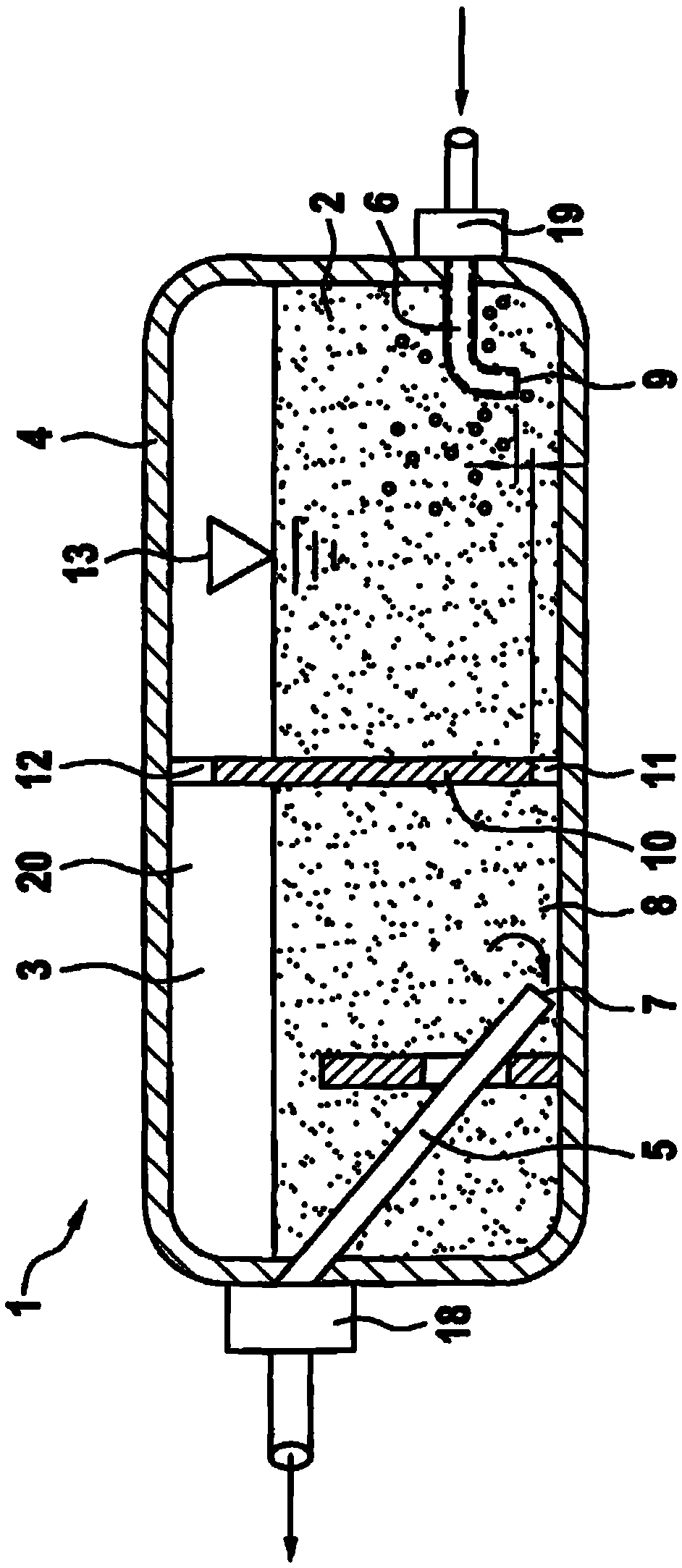
The invention relates to a storage tank (1) for a cryogenic medium (2), in particular for liquid natural gas, comprising a tank wall (4) delimiting a tank interior (3), at least one first pipe (5) andone second pipe (6) run through the tank wall to be guided into the tank interior, the first pipe (5) is used for removal of the medium (2) in liquid form and defines a removal point (7) which is arranged in a bottom region (8) of the tank interior (3). According to the invention, the second pipe (6) serves to recirculate a gaseous leakage quantity of the medium (2) and defines at least one injection point (9) which is also arranged at a distance (a) from the removal point (7) in the bottom region (8).

Description

technical field [0001] The invention relates to a storage tank for cryogenic media. The cryogenic medium can in particular be liquid natural gas (LNG), which is suitable for storage in motor vehicles as fuel for internal combustion engines. Background technique [0002] Motor vehicles, the internal combustion engines of which are operated on gaseous fuels, such as natural gas (NG, “Natural Gas”), are sufficiently known from the prior art. The natural gas can be stored in liquid state (LNG, “Liquid Natural Gas”) or in gaseous state (CNG, “Compressed Natural Gas”) in at least one tank carried on board the motor vehicle. Storage in liquid form has the advantage that the space requirement is low. However, natural gas first has to be cooled to temperatures below -161°C in order for it to be liquefied. [0003] Laid-open document DE 101 05 819 A1 discloses a device for refueling a vehicle operated with condensed fuel, which comprises a vacuum-insulated condensate tank mounted o...

Claims


Application Information

Patent Timeline
Patent Type & Authority Applications(China)
IPC IPC(8): F17C1/00F17C5/02F17C7/02F17C13/00
CPCF17C1/00F17C5/02F17C7/02F17C13/00F17C2221/033F17C2223/0161F17C2265/066F17C13/005F17C2201/0104F17C2201/0147F17C2201/0171F17C2201/035F17C2201/056F17C2205/035F17C2205/0391F17C2223/033F17C2223/047F17C2225/0123F17C2225/046F17C2227/0374F17C2250/0636F17C2260/02F17C2270/0168
Inventor J·韦斯内尔M·卡茨
Owner ROBERT BOSCH GMBH
Learn More