Liner tube for inlet channel of plate heat exchanger

A technology for plate heat exchangers and access channels, which can be applied to heat exchange equipment, heat exchanger shells, indirect heat exchangers, etc., and can solve problems affecting the performance of coolers

Inactive Publication Date: 2019-01-15
MAHLE INT GMBH
View PDF9 Cites 1 Cited by
  • Summary
  • Abstract
  • Description
  • Claims
  • Application Information

AI Technical Summary

Problems solved by technology

This creates a pressure drop in the heat exchanger module and thus affects the performance of the cooler
This is a significant disadvantage especially in the case of large-sized plate heat exchangers

Method used


Image

  • Liner tube for inlet channel of plate heat exchanger
  • Liner tube for inlet channel of plate heat exchanger

Examples


Embodiment Construction

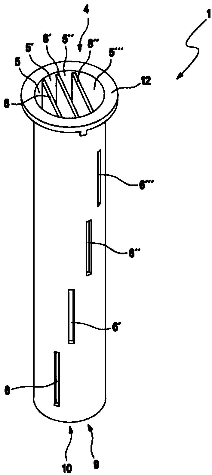
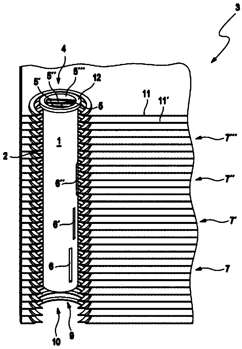
[0024] figure 1 A perspective view of a liner 1 according to the invention is shown from above at an angle onto its front open side 4 . The interior of the liner 1 is divided over its length into a total of four chambers 5, 5', 5" and 5"' by three secant partition walls 8, 8' and 8", wherein the lower end of the liner 1 is Closed, therefore closed on its rear side 10, except for the discharge opening 9 (not visible) communicating with the respective chambers 5, 5', 5" and 5"'. At different positions in relation to the chambers , the liner 1 has slit-like openings 6, 6', 6" and 6"', through which openings can be stacked on the corresponding plates 7, 7', 7" and 7"' ( figure 2 shown) distributes the refrigerant entering on its front open side 4. Thus, the flange section 12 formed on the front opening side 4 of the liner 1 is designed in such a way that the refrigerant mass flow is in the longitudinal direction of the individual chambers 5, 5', 5" and 5"' Oriented so as to be...


PUM


Abstract

The invention relates to a liner tube (1) for an inlet channel (2) of a plate heat exchanger (3), including an open front side (4) for supplying and discharging a refrigerant mass flow, an closed or at least partially closed rear side (10), wherein the liner tube (1) is divided into at least two bag-like chambers (5.....5'') extending in a longitudinal direction of the liner tube (1), communicating with the open front side (4) of the liner tube (1) in respective cases, having openings (6.....6'') at chamber-dependent different positions for distributing the refrigerant mass flow in plate stacks (7.....7'') of the plate heat exchanger (3). The invention also relates to a plate heat exchanger 3 comprising the liner tube (1) and its preferred use for regulating the temperature of an electricand/or fuel cell vehicle. Therefore, it is important for the invention to obtain as uniform distribution of a refrigerant two-phase mixture as possible independent of the mass flow crossing the platestacks (7.....7'') of the plate heat exchanger (3).

Description

technical field [0001] The invention relates to a liner for an inlet channel of a plate heat exchanger according to claim 1 . The invention also relates to a plate heat exchanger according to claim 9 comprising such a liner and to the use of such a plate heat exchanger according to claim 13 for temperature regulation. Background technique [0002] In the field of thermal management of electric and fuel cell vehicles, plate (disk) heat exchangers (transfer units), so-called coolers, which dissipate heat from the coolant into the evaporating refrigerant, are becoming more and more common. Especially fast charging, which generates a lot of heat in a short period of time due to it, poses a major challenge to the cooler. This case requires a large cooler with multiple plates. The refrigerant two-phase mixture must be distributed across the plates, ie ideally the fractions of gas and liquid phases should be the same (in height) on each plate. However, only very low waste heat r...

Claims


Application Information

Patent Timeline
Patent Type & Authority Applications(China)
IPC IPC(8): F28D9/00F28F9/02
CPCF28D9/00F28F9/028F28D1/03F28D2021/0043F28D2021/0028F28F2009/224F28D2021/008F28D1/0375H01M8/04067H01M2220/20H01M2250/20H01M10/65F28F9/0273F28F9/0246H01M10/625H01M10/663F28F9/0265Y02T90/40Y02E60/50Y02E60/10F28F9/0278G03F7/70925
Inventor 蒂莫·费尔德克勒多米尼克·贝纳特
Owner MAHLE INT GMBH
Why Eureka
Try Eureka