Eureka AIR delivers breakthrough ideas for toughest innovation challenges, trusted by R&D personnel around the world.

Weight loading control mechanism

A control mechanism and weight technology, applied in measuring devices, instruments, weighing, etc., can solve the problems of uncertain damping of cylinder and piston, poor calculation accuracy of loading moment, unstable air pressure, etc., and achieve the elimination of measurement results and accuracy Effects, easy to use, easy to load effects

Pending Publication Date: 2019-01-15
FUJIAN LONGXI BEARING (GROUP) CO LTD
View PDF0 Cites 2 Cited by
  • Summary
  • Abstract
  • Description
  • Claims
  • Application Information

AI Technical Summary

Problems solved by technology

[0005] The existing pneumatic pendulum-type centripetal joint bearing radial clearance measuring instrument uses the air pressure loading method, the air pressure is unstable and the damping of the cylinder and piston is uncertain, and the influence of the gravity of the outer ring of the joint bearing on the load is not considered in the whole process. The measurement accuracy of the radial clearance is low, and it is not suitable for the measurement of the radial clearance of high-precision radial spherical plain bearings
[0006] The existing unequal-arm lever-type radial joint bearing axial clearance measuring instrument uses a rod weighing mechanism to load the distributed load of the swimming weight, so that the calculation accuracy of the loading moment is poor, and the obtained axial clearance measurement accuracy is low , not suitable for the measurement of radial clearance of high-precision radial spherical plain bearings

Method used


Image

  • Weight loading control mechanism
  • Weight loading control mechanism
  • Weight loading control mechanism

Examples


Embodiment Construction

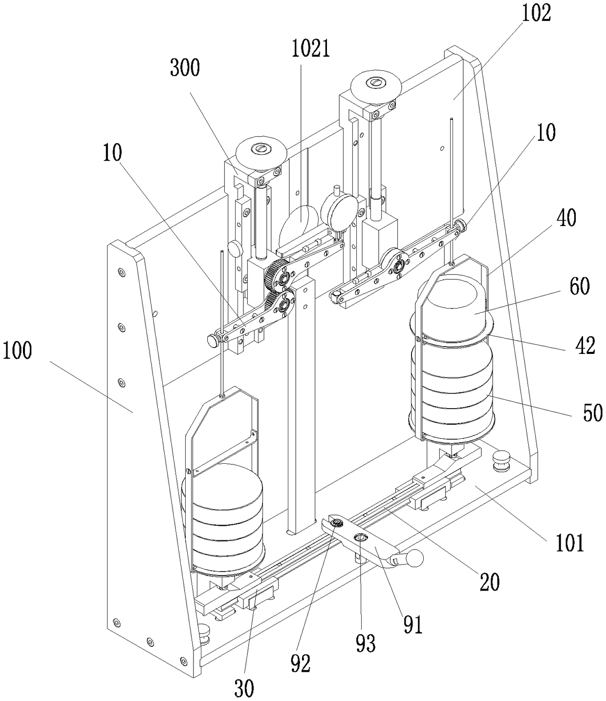
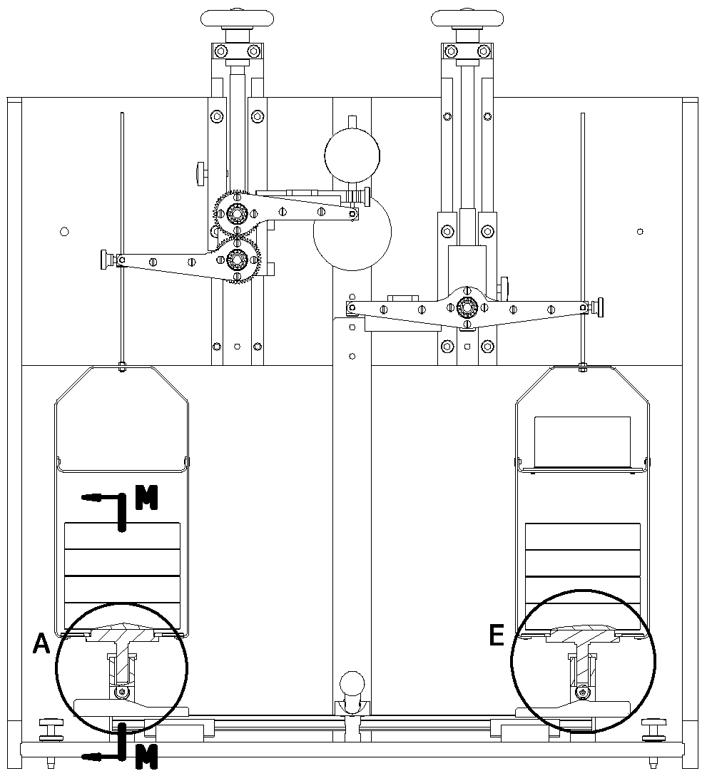
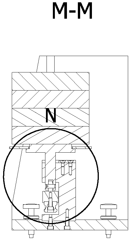
[0041] Please check Figure 1 to Figure 12 , a weight loading control mechanism, comprising:

[0042] Frame 100, two horizontal force arms 10 installed on the frame 100, each end of the two horizontal force arms 10 forms a point of application of force respectively and can form a relative force parallel to the direction of gravity, that is, the two force application points can apply force And can form opposite force;

[0043] Slide bar 20, slide seat 30, this slide bar 20 is arranged horizontally and is slidably connected with this slide seat 30, has first cam 21 and second cam 22 respectively at both ends, and this first cam 21 includes from one end of slide bar 20 Connected first plane 211, first transitional surface 212 and second plane 213, the second cam 22 includes a third plane 221, a second transitional plane 222, a fourth plane 223, The third transition surface 224 and the fifth plane 225, the first plane 211 is higher than the level of the second plane 213 and cons...


PUM


Abstract

The invention discloses a weight loading control mechanism, which comprises a rack, two horizontal force arms, a sliding rod, a sliding seat, two weight disks, loading weights, a gravity weight, two trays, two idler wheels and a handle mechanism. The sliding rod is slidably connected with the sliding seat, and the two ends of the sliding rod are provided with a first cam and a second cam correspondingly. The weight disks are suspended on the horizontal force arms, through holes are formed in base plates of the weight disks, and a layer plate used for storing the gravity weight is further arranged in one of the weight disks. The trays are stepped trays, and the lower end of each tray is provided with a guide column in an extending mode, wherein the tail end of the guide column is connectedwith the corresponding idler wheel. The two idler wheels are arranged on the first cam and the second cam correspondingly and can roll horizontally and transversely. The upper stepped faces of the stepped trays movably stretch into or out of the through holes, and the diameters of the lower stepped faces of the stepped trays are larger than those of the base plates of the weight disks. The handlemechanism is connected with the sliding rod to drive the sliding rod to move horizontally and transversely. The weight loading control mechanism has the following advantages that accurate loading of the preset load can be achieved, and loading operation is easy and convenient.

Description

technical field [0001] The invention relates to the field of weighing equipment, in particular to a weight loading control mechanism. Background technique [0002] The radial joint bearing is a sliding bearing with a spherical clearance fit to achieve the self-aligning performance (ie universality) of the supporting shaft within a certain range. The clearance of radial spherical plain bearing is one of the main indicators to measure its quality, and it needs to be measured and verified by professional equipment (instrument). At present, there are two types of clearance measurement items for radial spherical plain bearings: radial clearance and axial clearance, which are measured by radial clearance measuring instruments and axial clearance measuring instruments respectively. [0003] The working principle of the pneumatic pendulum-type radial clearance measuring instrument for radial joint bearings is to put the inner ring hole of the radial joint bearing to be measured and...

Claims


Application Information

Patent Timeline
Patent Type & Authority Applications(China)
IPC IPC(8): G01G21/18G01G21/23
CPCG01G21/18G01G21/23
Inventor 蔡士源陈伍钦吴世榕邱志辉
Owner FUJIAN LONGXI BEARING (GROUP) CO LTD
Why Eureka
Eureka Blog
Learn More