
An electrified railway in-phase power supply and transformation system

A technology for electrified railways and substation systems, applied in flexible AC transmission systems, electrical components, circuit devices, etc., can solve problems such as the restriction of the number of traction substation groups, the limitation of electrified railway mileage, and the poor economic indicators of network loss. Superior performance, ease of implementation, and reduced power consumption

Pending Publication Date: 2019-01-15
SOUTHWEST JIAOTONG UNIV
View PDF2 Cites 10 Cited by
  • Summary
  • Abstract
  • Description
  • Claims
  • Application Information

AI Technical Summary

Problems solved by technology

The study found that when the scale of the traction substation group is larger, the scale of active power flow that needs to be changed is larger, the electrical distance is longer, the technical difficulty is greater, and the economic index of network loss is worse, or even impossible; at the same time , since the same substation in the power grid supplies power to multiple traction substations in a radial structure, it will be limited by the length of the radial high-voltage transmission line and the investment, so that the number of traction substations is restricted, which also makes the use of The mileage of the electrified railway that cancels the electric split phase here is limited due to the bilateral connection technology

Method used


Image

  • An electrified railway in-phase power supply and transformation system
  • An electrified railway in-phase power supply and transformation system
  • An electrified railway in-phase power supply and transformation system

Examples


Embodiment Construction

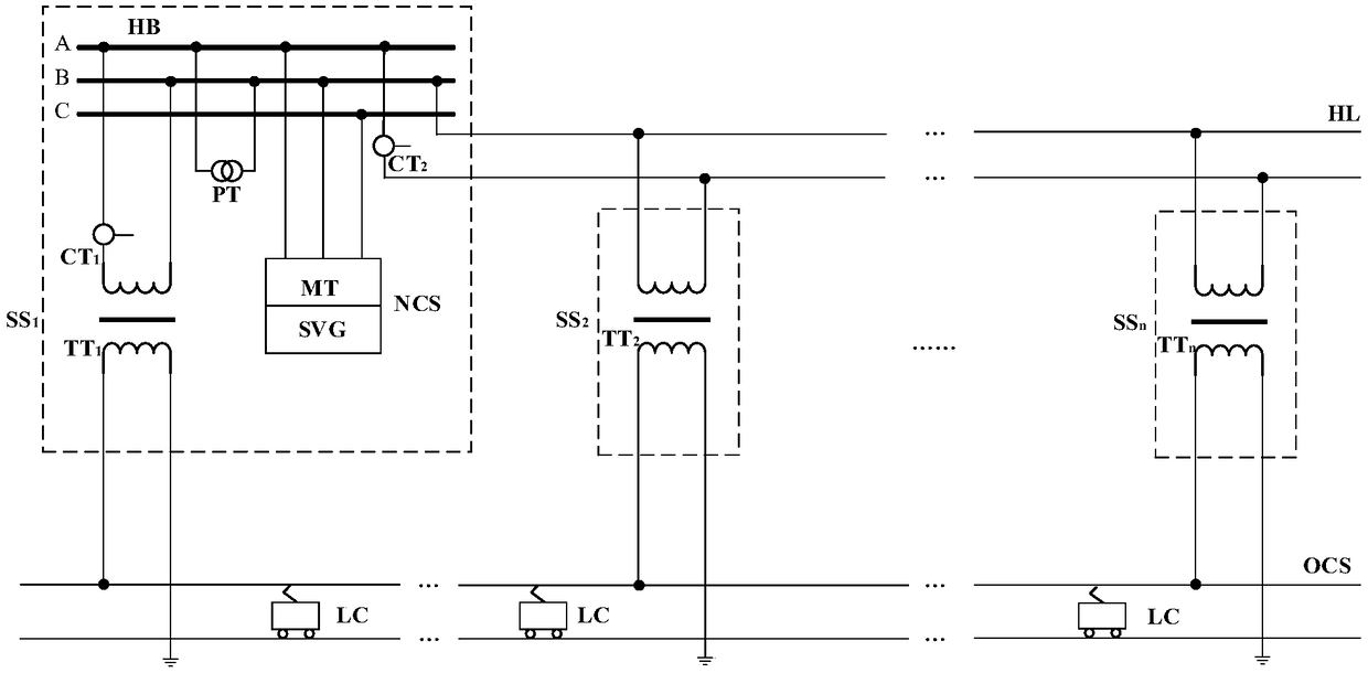
[0027] In order to better understand the creative idea of ​​the present invention, the working principle of the present invention is: the power factor of the AC-DC train is very high, which can be considered as 1, and the power factors of each traction substation are the same, and the three-phase high-voltage bus PCC (negative sequence assessment point), the total negative sequence current generated at the PCC can be calculated with scalar algebra, and the total negative sequence current or power can be centrally compensated in a traction substation by installing a negative sequence compensation system. After compensation, it meets the national standard requirements, where Negative-sequence compensation generates negative-sequence power flow through its three-phase reactive power compensation device, which does not change the active power flow of the same-phase power supply and transformation system. Railway power supply mileage.

[0028] The present invention will be further ...


PUM


Abstract

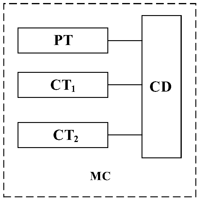
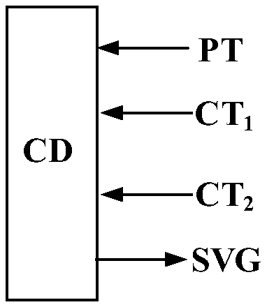
The invention discloses an electrified railway in-phase power supply and transformation system, which relates to the technical field of AC electrified railway power supply. The in-phase power supply and transformation system comprises n traction substations, a single-phase high-voltage transmission line and a traction network, wherein, the first traction substation comprises a three-phase high-voltage bus bar, a first main transformer connected with the three-phase high-voltage bus bar and a negative sequence compensation device connected with the three-phase high-voltage bus bar; The second traction substation to the nth traction substation are respectively connected with the single-phase high-voltage transmission line and the traction network. The negative sequence compensation device isinstalled in the first traction substation, and comprises a three-phase compensation transformer, a three-phase reactive power compensation device and a measurement and control unit. The negative sequence compensation device generates the negative sequence power flow through the three-phase reactive power compensation device, and does not change the active power flow of the whole system; At the same time, the power supply mileage of electrified railway without phase separation is greatly prolonged by using the advantages of large transmission power and long transmission distance of high voltage transmission line.

Description

technical field [0001] The invention relates to the technical field of AC electrified railway power supply, in particular to high-voltage, long-distance in-phase power supply and transformation technology. Background technique [0002] Electrified railways generally adopt the single-phase power frequency AC system powered by the public power system. In order to make the single-phase traction load be distributed as balanced as possible in the three-phase power system, the electrified railway often adopts the scheme of rotating phase sequence and separate phase and partition power supply. The adjacent power supply areas at the phase-splitting partitions are separated by phase-splitting insulators to form electrical phase-splitting, referred to as phase-splitting. The electric phase separation link is the weakest link in the entire traction power supply system, and the excessive phase separation of trains has become the bottleneck of traction power supply for high-speed railway...

Claims


Application Information

Patent Timeline
Patent Type & Authority Applications(China)
IPC IPC(8): H02J3/18H02J3/06
CPCH02J3/06H02J3/1821Y02E40/10Y02E40/30
Inventor 李群湛李晋解绍锋刘刚郭锴宫衍圣陈民武黄文勋黄小红周志录易东
Owner SOUTHWEST JIAOTONG UNIV
Learn More