Scanning probe microscope

A probe microscope, scanning technology, applied in the field of scanning probe microscope, can solve the problem of not necessarily obtaining the surface image of the sample, inaccuracy, etc.

Inactive Publication Date: 2019-01-15
SHIMADZU SEISAKUSHO CO LTD
View PDF10 Cites 0 Cited by
  • Summary
  • Abstract
  • Description
  • Claims
  • Application Information

AI Technical Summary

Problems solved by technology

Therefore, sometimes the inaccurate image data in the tracking image data and the retrace image data may be selected, and an accurate sample surface image may not be obtained
[0009] In addition, when the value of the tracking image data in a certain part exceeds a prescribed threshold, the retrace image data obtained for that part may not necessarily represent the surface shape of the sample more accurately.
Therefore, even in the case of using the above-mentioned other methods in Patent Document 1, inaccurate image data among the tracking image data and the retrace image data may sometimes be selected, and an accurate sample surface image may not always be obtained.

Method used


Image

  • Scanning probe microscope
  • Scanning probe microscope
  • Scanning probe microscope

Examples


no. 1 example

[0044] Hereinafter, a first embodiment of a scanning probe microscope (SPM) according to the present invention will be described with reference to the drawings.

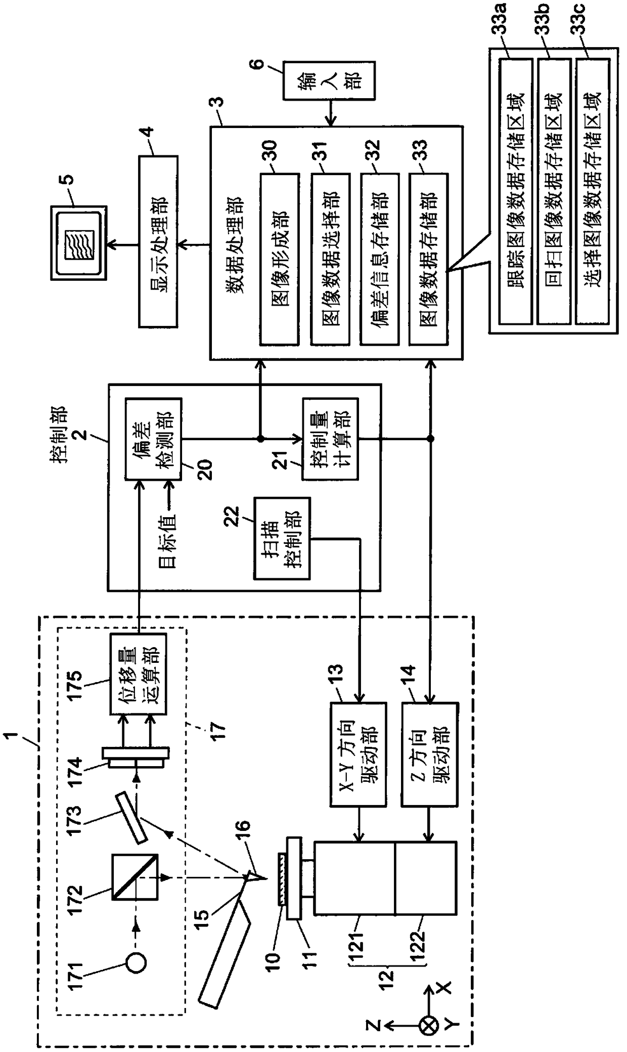
[0045] figure 1 is a structural diagram of the main part of the SPM of the first embodiment.

[0046] In the measurement unit 1 , a sample 10 to be measured is placed on a sample stage 11 provided on a scanner 12 . The scanner 12 includes an XY scanner 121 that moves the sample 10 in two axial directions of X and Y that are perpendicular to each other in a plane parallel to the upper surface of the sample stage 11, and moves the sample 10 in the direction of the X axis and the Y axis. The Z scanner 122 moves slightly in the Z-axis direction perpendicular to the Y-axis. The XY scanner 121 and the Z scanner 122 respectively use piezoelectric elements that are displaced by voltages applied from the X-Y direction driving unit 13 and the Z direction driving unit 14 as drive sources.

[0047] A flexible cantilever 15 h...

no. 2 example

[0067] Figure 5 is a structural diagram of the main part of the SPM of the second embodiment. Structural elements that are the same as or equivalent to those of the SPM of the first embodiment described above are given the same reference numerals, and description thereof will be omitted unless particularly necessary. The SPM performs sample surface shape measurements in dynamic mode. Therefore, the vibration control unit 23 drives a piezoelectric element (not shown) attached to the cantilever 15 to vibrate the cantilever 15 at a predetermined frequency. In addition, the amplitude calculation unit 24 obtains the amplitude of the vibration of the cantilever 15 during the above-mentioned excitation based on the displacement obtained by the displacement calculation unit 175 . The deviation detection unit 20 obtains a deviation between the vibration amplitude and the target amplitude value, and performs feedback control so that the deviation becomes zero.

[0068] The deviation...

no. 3 example

[0070] In the first embodiment and the second embodiment, in order to measure the shape of the sample surface, the selection of the tracking image data and the retrace image data is performed using the deviation obtained in the closed loop for feedback control of the Z scanner 122, but It is also possible to select highly accurate image data by using other data reflecting the physical property information of the sample surface that can be acquired by SPM instead of the deviation.

[0071] Figure 6 is a structural diagram of the main part of the SPM of the third embodiment. In this SPM, selection of image data is performed using data obtained by measurement by phase mode, and measurement by phase mode can be performed in parallel with measurement of sample surface shape by dynamic mode.


PUM


Abstract

In the present invention, when trace image data is acquired while using a probe (16) to scan an area on a sample (10) in a forward direction and retrace image data is acquired while scanning the samearea in the reverse direction, a deviation information storage unit (32) stores deviation detected by a deviation detection unit (20). This deviation is an indication of the difference between the distance between the probe and the sample and a target value for the distance at a given point in time. An image data selection unit (31) compares the deviation during forward scanning and the deviationduring reverse scanning for each measurement point, selects the image data acquired during scanning that has the smallest deviation, and stores the same to a storage area (33c) of an image data storage unit (33) as selected image data. An image formation unit (30) creates a sample surface shape image on the basis of the selected image data and displays the same on a display unit (5). As a result,even if there is a steep recess or protrusion on a sample (10) and there is a tracking delay or disturbance in the feedback control for the distance between the probe and the sample, it is possible todisplay an accurate image close to the actual shape of the surface of the sample.

Description

technical field [0001] The present invention relates to a scanning probe microscope, and more specifically, to a processing technique for image data reflecting the surface shape of a sample obtained in a scanning probe microscope. Background technique [0002] Scanning Probe Microscope (hereinafter referred to as "SPM") brings the tip of a tiny probe (probe) close to the surface of the sample, and detects the mechanical or electromagnetic interaction between the probe and the sample. The probe is used to scan the surface of the sample to observe the shape of the sample surface, the distribution of electrical characteristics, and the like. In an atomic force microscope (Atomic Force Microscope, hereinafter abbreviated as "AFM"), which is a typical SPM, atomic force is measured as an interaction between a probe and a sample surface (see Non-Patent Document 1, etc.). [0003] AFM generally has a scanner that moves the sample in the three-axis directions of X, Y, and Z that are...

Claims


Application Information

Patent Timeline
Patent Type & Authority Applications(China)
IPC IPC(8): G01Q30/04G01B5/20
CPCG01Q30/06G01B5/20G01Q10/06G01Q20/02G01Q30/18
Inventor 新井浩
Owner SHIMADZU SEISAKUSHO CO LTD
Why Eureka
Try Eureka