Orthopedic surgery positioning punching device

A drilling device and orthopedic surgery technology, applied in surgery, medical science, bone drill guidance, etc., can solve problems such as easy deviation, unfavorable surgery, and strong pain in patients, so as to achieve convenient operation and relieve pain Effect

Inactive Publication Date: 2019-01-18
山东大学齐鲁医院(青岛)
View PDF4 Cites 9 Cited by
  • Summary
  • Abstract
  • Description
  • Claims
  • Application Information

AI Technical Summary

Problems solved by technology

[0002] Bone drilling is a common procedure in orthopedic surgery. It is necessary to drill the bone before screwing the bolt or steel plate into the patient's leg. At present, people mainly use the drill to drill the patient's bone. When using the drill, It is difficult for the doctor to accurately control the angle of the drill bit, and it is easy to cause deviation to affect the operation; in

Method used


Image

  • Orthopedic surgery positioning punching device
  • Orthopedic surgery positioning punching device
  • Orthopedic surgery positioning punching device

Examples


Embodiment 1

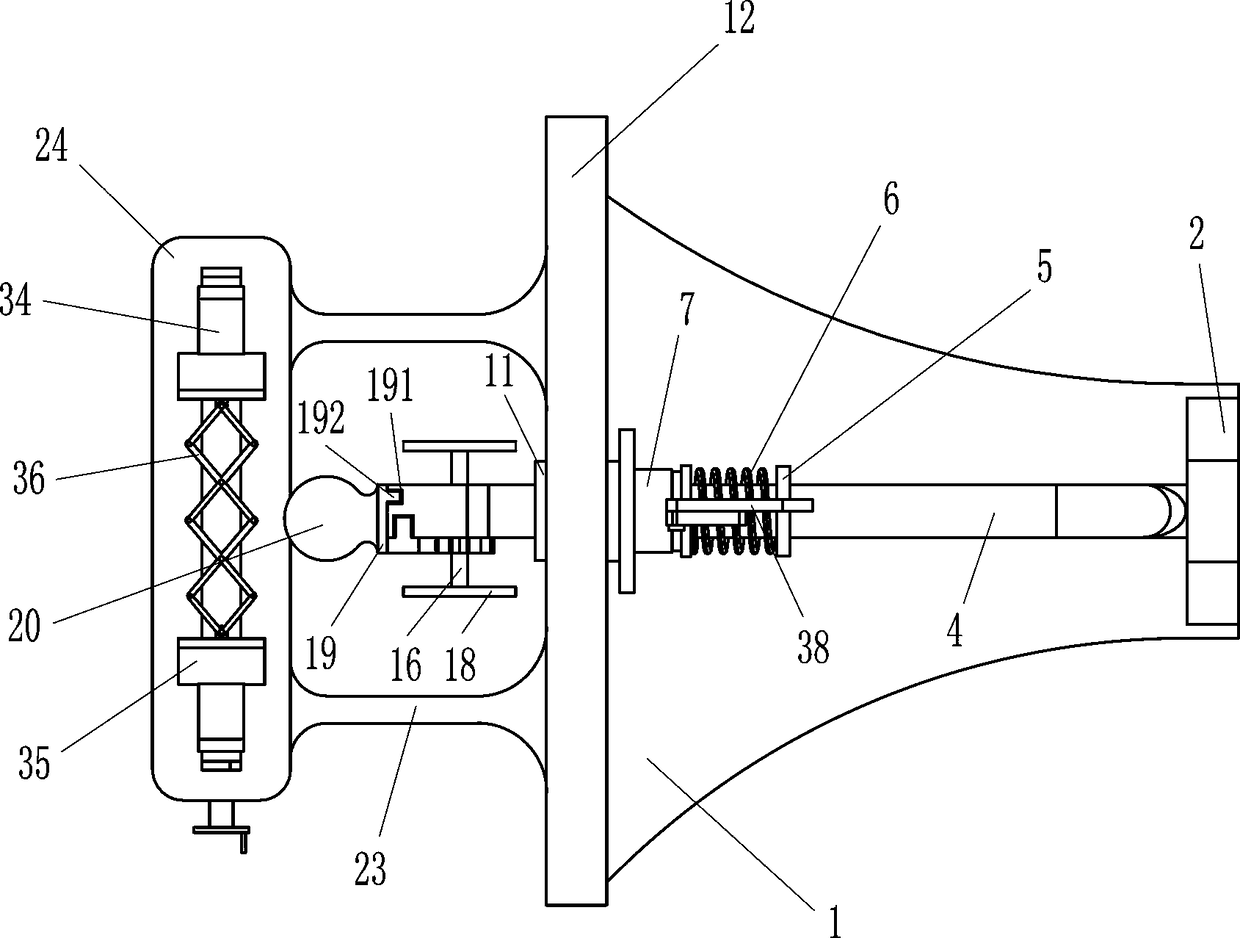
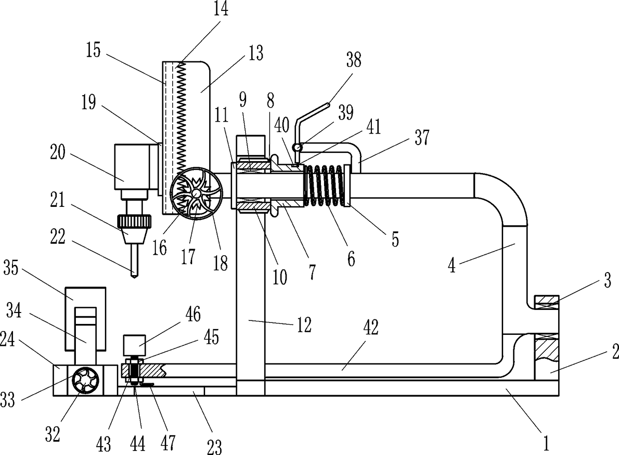
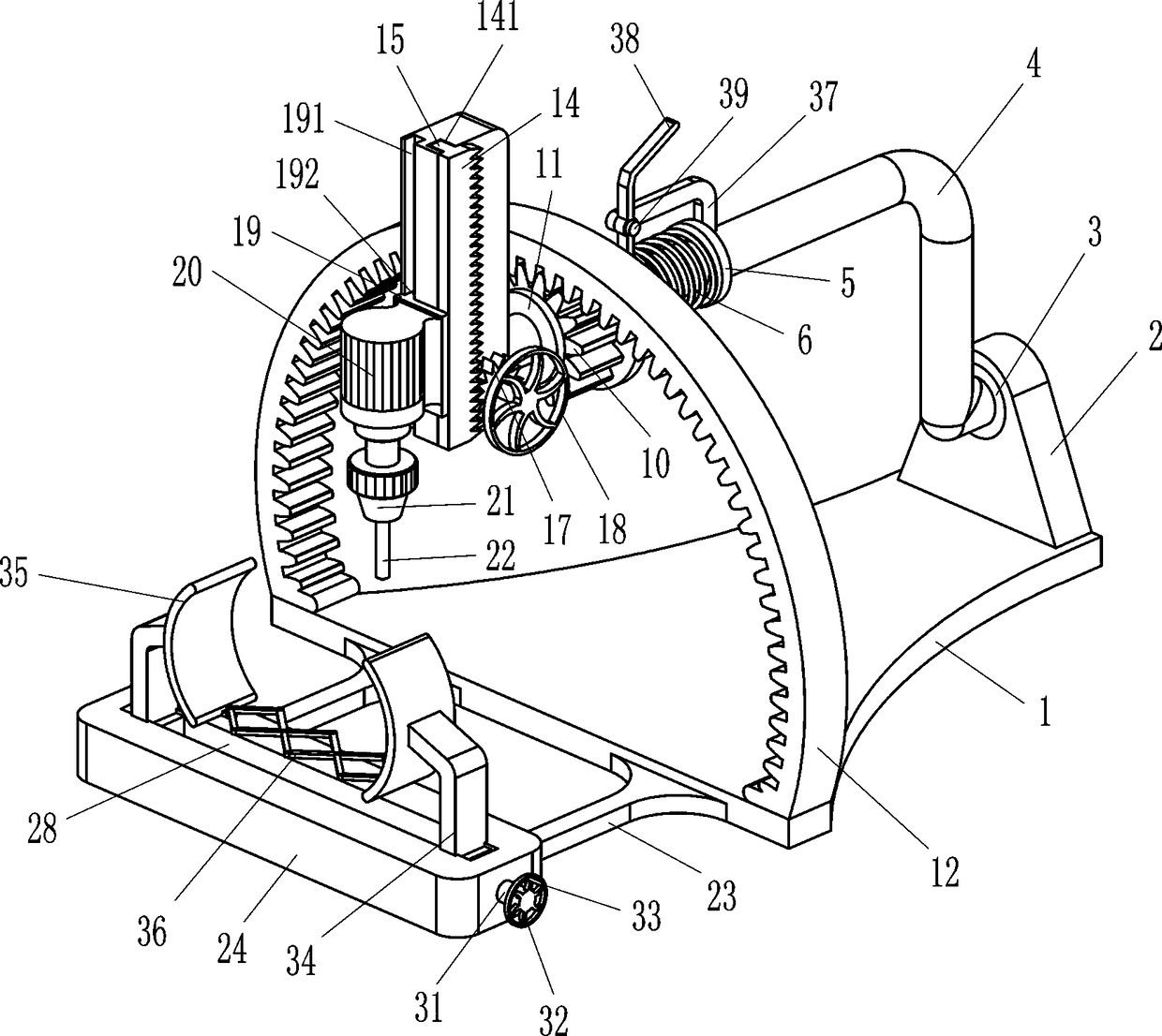
[0018] A positioning punching device for orthopedic surgery, such as Figure 1-4 As shown, it includes a base 1, a tailstock 2, a first bearing seat 3, an upper L-shaped cylindrical rod 4, a first limit block 5, a compression spring 6, a sleeve 7, an insert block 8, a second bearing seat 9, The first pinion 10, the second limit block 11, the half ring gear 12, the first mounting plate 13, the rack 14, the first slider 15, the mandrel 16, the second gear 17, the first turning handle 18, the first Second mounting plate 19, second slider 192, forward and reverse motor 20, chuck 21, drill bit 22, connecting plate 23, front mounting plate 24, third slider 27, third bearing seat 30, positive and negative screw rod 31. The second turning handle 32, the handle protrusion 33, the connecting block 34, the first protective gear 35 and the telescopic support frame 36, the tailstock 2 is installed on the right side of the base 1, and the first bearing seat 3 is installed on the upper part ...

Embodiment 2

[0020] A positioning punching device for orthopedic surgery, such as Figure 1-4 As shown, it includes a base 1, a tailstock 2, a first bearing seat 3, an upper L-shaped cylindrical rod 4, a first limit block 5, a compression spring 6, a sleeve 7, an insert block 8, a second bearing seat 9, The first pinion 10, the second limit block 11, the half ring gear 12, the first mounting plate 13, the rack 14, the first slider 15, the mandrel 16, the second gear 17, the first turning handle 18, the first Second mounting plate 19, second slider 192, forward and reverse motor 20, chuck 21, drill bit 22, connecting plate 23, front mounting plate 24, third slider 27, third bearing seat 30, positive and negative screw rod 31. The second turning handle 32, the handle protrusion 33, the connecting block 34, the first protective gear 35 and the telescopic support frame 36, the tailstock 2 is installed on the right side of the base 1, and the first bearing seat 3 is installed on the upper part ...

Embodiment 3

[0023] A positioning punching device for orthopedic surgery, such as Figure 1-4As shown, it includes a base 1, a tailstock 2, a first bearing seat 3, an upper L-shaped cylindrical rod 4, a first limit block 5, a compression spring 6, a sleeve 7, an insert block 8, a second bearing seat 9, The first pinion 10, the second limit block 11, the half ring gear 12, the first mounting plate 13, the rack 14, the first slider 15, the mandrel 16, the second gear 17, the first turning handle 18, the first Second mounting plate 19, second slider 192, forward and reverse motor 20, chuck 21, drill bit 22, connecting plate 23, front mounting plate 24, third slider 27, third bearing seat 30, positive and negative screw rod 31. The second turning handle 32, the handle protrusion 33, the connecting block 34, the first protective gear 35 and the telescopic support frame 36, the tailstock 2 is installed on the right side of the base 1, and the first bearing seat 3 is installed on the upper part o...


PUM


Abstract

The invention relates to a punching device, and especially relates to an orthopedic surgery positioning punching device. The technical problem of the present invention is to provide an orthopaedic surgical positioning and punching device which can stably punch a drill bit, stably adjust a drilling angle, and has a support device capable of alleviating pain. A technical scheme: an orthopedic surgical position punching device comprise a base, a tail, a first bearing seat, an upper L-shaped cylindrical rod, a first limit block, a compression spring, a sleeve, a plug, a second bearing seat, a first pinion, etc. A tail seat is arrange on that right side of the base, a first bearing seat is arrange on the upper part of the tail seat, and an upper L-shaped cylindrical rod is arranged in the firstbearing seat. As that plug block is arrange, the plug block contacts with the first pinion gear when people do not use the equipment, so that the first pinion gear can be prevented from move at willon the semi-ring gear, and as the toggle bar is arranged, the sleeve can be driven to move by rotating the toggle bar, so that the equipment can carry out subsequent work and is convenient for peopleto operate.

Description

technical field [0001] The invention relates to a punching device, in particular to a positioning punching device for orthopedic surgery. Background technique [0002] Bone drilling is a common procedure in orthopedic surgery. It is necessary to drill the bone before screwing the bolt or steel plate into the patient's leg. At present, people mainly use the drill to drill the patient's bone. When using the drill, It is difficult for the doctor to accurately control the angle of the drill bit, and it is easy to cause deviation to affect the operation; in order to control the angle of the drill bit without deviation, the doctor usually needs to use the guide to guide at the same time, and it is troublesome for the doctor to control the drill while controlling the guide. , is not conducive to surgery; when people are performing drilling surgery, there is no corresponding equipment for auxiliary support, which makes the patient feel more pain. Contents of the invention [0003...

Claims


Application Information

Patent Timeline
IPC IPC(8): A61B17/16A61B17/17
CPCA61B17/1655A61B17/1659A61B17/171
Inventor 康立茂
Owner 山东大学齐鲁医院(青岛)
Why Eureka
Try Eureka