
Steel form cutting machine special for trailers

A technology of cutting machine and steel mold, which is applied in the field of steel processing, can solve the problems that section steel is piled up under the cutting mold or mold, there is no supporting feeding mechanism and discharging mechanism, and the dimensional accuracy of section steel is affected, so as to improve cutting efficiency and control The effect of high precision and improvement of overall quality

Inactive Publication Date: 2019-01-18
石家庄金丰专用车有限公司
View PDF12 Cites 0 Cited by
  • Summary
  • Abstract
  • Description
  • Claims
  • Application Information

AI Technical Summary

Problems solved by technology

[0006] Although the above two kinds of cutting equipment overcome the defects of grinding wheel cutting machine, flame cutting machine and sawing machine cutting equipment, both of them have no supporting feeding mechanism and discharging mechanism, resulting in the accumulation of cut section steel under the cutting die or mold , affecting the cutting efficiency
And there is no matching limit, receiving or supporting device in the design. As we all know, the profile steel obtained through preliminary processing is a profile with a length of more than 2 meters. There is no force point for medium-sized steel, and it is difficult to generate stress that is assisted by the die force during the cutting process, resulting in the adhesion of the cut-off point of the shaped steel and it is difficult to take off; The dimensional accuracy of the section steel, and the section steel is randomly scattered and piled up after cutting, and the incision will have burrs due to the offset of the section steel, which will affect the overall quality of the steel mold

Method used


Image

  • Steel form cutting machine special for trailers
  • Steel form cutting machine special for trailers
  • Steel form cutting machine special for trailers

Examples


Embodiment Construction

[0039] In describing the invention, it is to be understood that the terms "centre", "upper", "lower", "front", "rear", "left", "right", "vertical", "horizontal" , "top", "bottom", "inner", "outer" and other indicated orientations or positional relationships are based on the orientations or positional relationships shown in the drawings, and are only for the convenience of describing the invention and simplifying the description, rather than indicating Or imply that the device or element referred to must have a specific orientation, be constructed and operate in a specific orientation, and therefore should not be construed as limiting the invention.

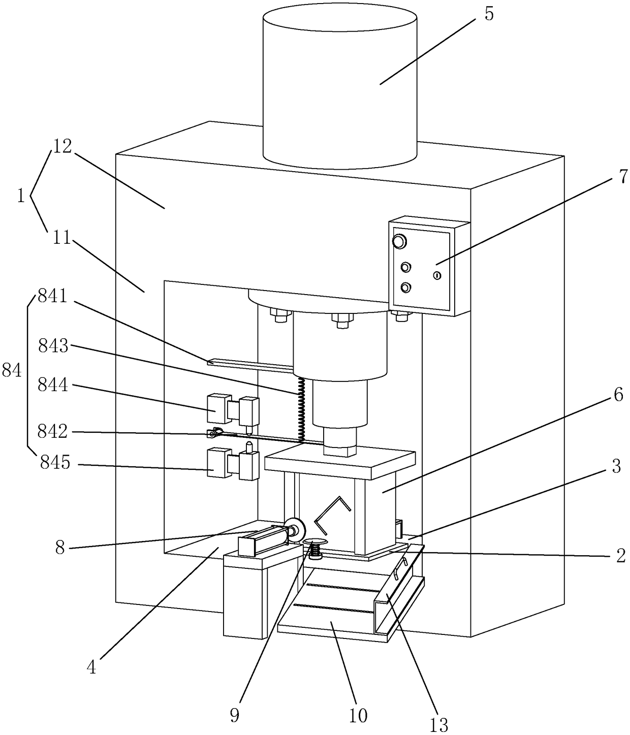
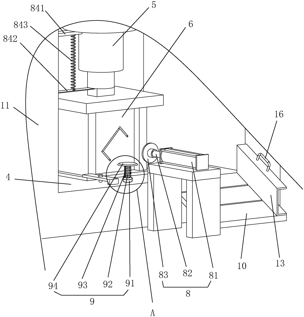
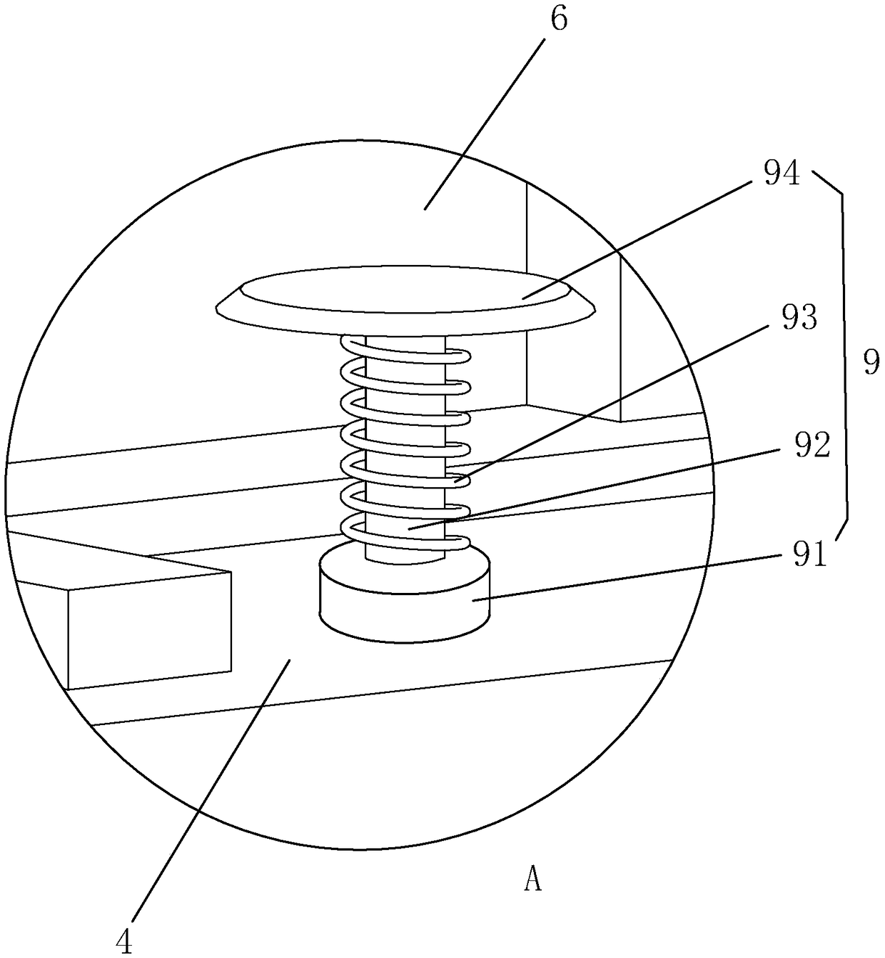
[0040] A special steel mold cutting machine for trailers, such as figure 1 As shown, it includes a frame 1, a cutting platform 2, a feeding platform 3, a discharging platform 4, an upper mold 5, a lower mold 6, a distribution box 7, a limiting device 8 and a receiving device 9. Frame 1 comprises the side frame 11 that is symmetri...


PUM


Abstract

The invention relates to the technical field of steel product processing, in particular to a steel form cutting machine special for trailers. The cutting machine comprises a machine frame, a cutting table, a feeding table, a discharging table, an upper die, a lower die and a discharging mechanism; the lower die is fixedly installed on the cutting table, and the upper die is installed at the upperend of the machine frame; the discharging mechanism is arranged on the discharging table; the discharging mechanism comprises a limiting device, and the limiting device is used for automatically abutting against the discharging end faces of workpieces; the discharging table is provided with a size-adjustable discharging plate, and the discharging plate is located on one side of the limiting device. By designing the feeding table and the discharging table in cooperation with the upper die and the lower die, the discharging table conveys different specifications of steel forms to a designated area after cutting, the cutting operation is not affected, and the cutting efficiency is improved; by designing the discharging mechanism on the discharging table, automatic abutting against the discharging ends of the workpieces is realized, skewing of the workpieces in the cutting process is avoided, and the quality of the steel forms is improved.

Description

technical field [0001] The invention relates to the technical field of steel processing, in particular to a special steel mold cutting machine for trailers. Background technique [0002] Channel steel is a long strip of steel with a groove-shaped cross-section. It belongs to carbon structural steel for construction and machinery. It is a section steel with complex cross-sections. . Because channel steel has good mechanical properties and performance, it has been widely used in building structures, engineering structures, curtain wall engineering, mechanical equipment and vehicle manufacturing. [0003] Processing and cutting section steel to meet the requirements of various specifications of structural parts such as building structures is the key to the processing and manufacturing of section steel. At present, the cutting machine equipment of channel steel mainly includes grinding wheel cutting machine, flame cutting machine and sawing machine and other types. The use of...

Claims


Application Information

Patent Timeline
IPC IPC(8): B21D28/04B21D45/00
CPCB21D28/04B21D45/00
Inventor 张成泽
Owner 石家庄金丰专用车有限公司
Learn More