Novel combined cutter bar

A combined type and tool holder technology, which is applied to the accessories of tool holders, turning equipment, metal processing equipment, etc., can solve the problems of inconvenient loading and unloading of the heat-shrinkable tool holder 100, and difficulty in taking out the tool 200, etc., to achieve enhanced rigidity and matching Stabilizing, performance-enhancing effects

Inactive Publication Date: 2019-01-18
SHENZHEN INSTITUTE OF INFORMATION TECHNOLOGY
View PDF12 Cites 4 Cited by
  • Summary
  • Abstract
  • Description
  • Claims
  • Application Information

AI Technical Summary

Problems solved by technology

However, the connecting screw 400 is arranged inside the knife handle 300, which is inconvenient for the loading and unloading of the heat-shrinkable knife holder 100.
In addition, once the cutter 200 breaks, it is difficult to remove the cutter 200 from the heat-shrinkable holder 100

Method used


Image

  • Novel combined cutter bar
  • Novel combined cutter bar
  • Novel combined cutter bar

Examples


Embodiment Construction

[0028] Now in conjunction with the accompanying drawings, the preferred embodiments of the present invention will be described in detail.

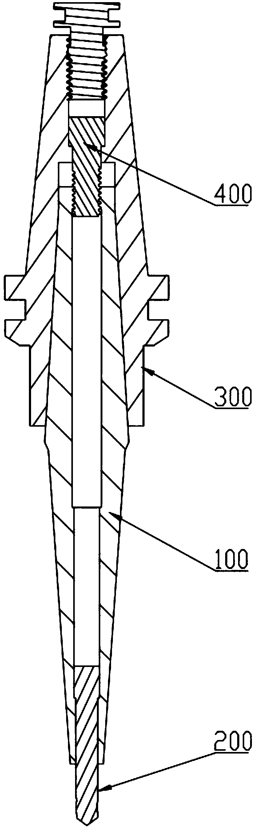
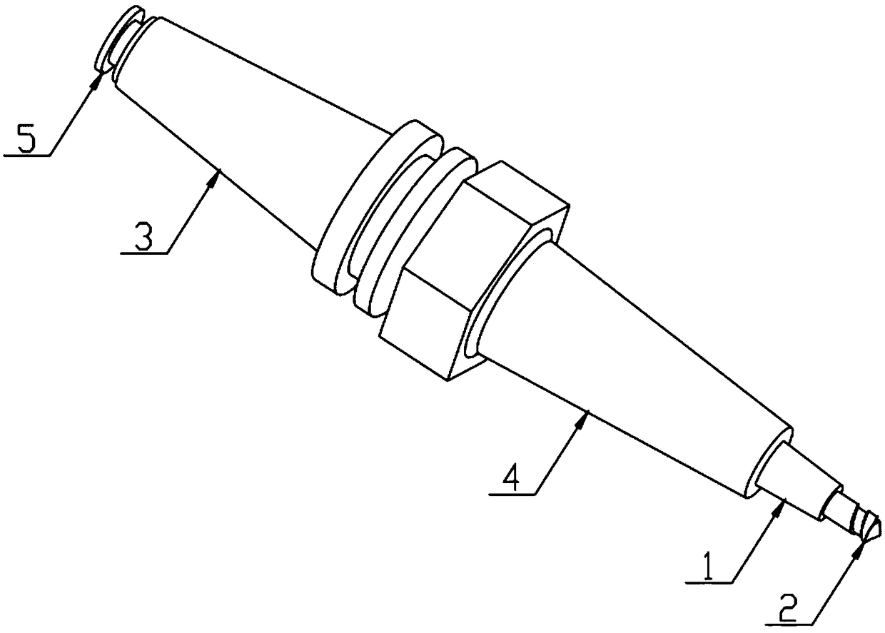
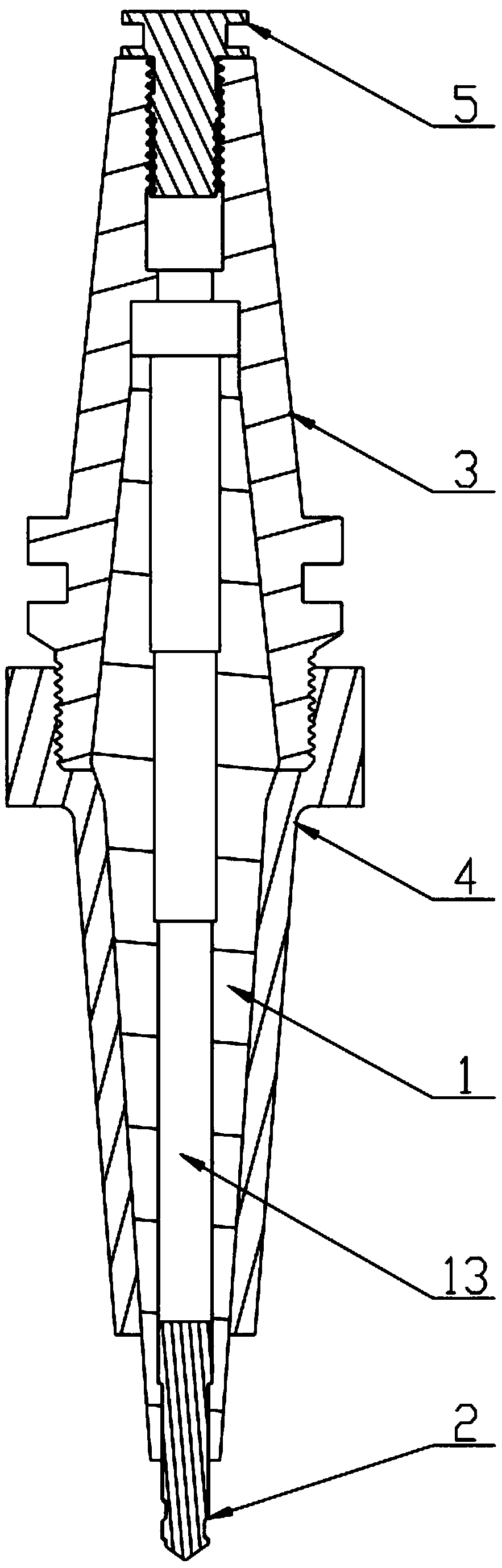
[0029] Such as Figure 2-5 As shown, the novel combined tool holder of this embodiment includes a heat shrinkable tool holder 1, a tool 2, a handle 3 and a sleeve 4; one end of the heat shrinkable cutter holder 1 is provided with a first tapered surface 11, and the other end is provided with a There is a second tapered surface 12, and a through hole 13 is opened inside along the axial direction; one end of the tool 2 is inserted into the through hole 13 through shrink fit, and the other end extends out of the through hole 13; the handle 3 The inside of the sleeve 4 is provided with a first tapered hole 31 matched with the first tapered surface 11, and is sleeved on the first tapered surface 11 through the first tapered hole 31; the inside of the sleeve 4 is provided with a second The second tapered hole 41 matched with the tapered surface...


PUM


Abstract

The invention particularly relates to a novel combined cutter bar. The novel combined cutter bar comprises a heat-shrinkable cutter bar body, a cutter, a cutter holder and a sleeve; one end of the heat-shrinkable cutter bar body is provided with a first tapered surface, the other end of the heat-shrinkable cutter bar body is provided with a second tapered surface, and the heat-shrinkable cutter bar body is internally provided with a through hole; one end of the cutter is inserted into the through hole, and the other end of the cutter stretches out of the through hole; the cutter holder is internally provided with a first tapered hole matched with the first tapered surface; the sleeve is internally provided with a second tapered hole matched with the second tapered surface; the sleeve and the cutter holder are detachably connected to make the inner wall of the first tapered hole fit the first tapered surface and the inner wall of the second tapered hole fit the second tapered surface. The first tapered hole fits the first tapered surface and the second tapered hole fits the second tapered surface, so that the whole heat-shrinkable cutter bar body is fastened, the performance of thecombination surface is improved, matching of the components is more stable, and the rigidity of a cutter system is improved. Moreover, the cutter holder and the sleeve are detachably connected, the heat-shrinkable cutter bar body can be taken out simply by disassembling the sleeve, and convenience is provided for the assembly and disassembly of the heat-shrinkable cutter bar body or even the replacement of the cutter.

Description

technical field [0001] The invention relates to the field of machining, in particular to a novel combined tool holder. Background technique [0002] In high-speed cutting, the tool system composed of tool holder-heat-shrinkable tool holder-tool is commonly used to process parts with deep cavity structure. A shrink shank is an intermediate clamping element that connects the tool holder to the tool. The heat-shrinkable tool holder has the characteristics of simple structure, high clamping accuracy, high clamping stability, high clamping strength and bending rigidity, high rotational balance, easy access to the workpiece, adaptability and deep cavity processing, etc., while the heat-shrinkable tool The fit between the shank and the tool holder is an important part of the study of the tool holding system. [0003] Such as figure 1 As shown, the traditional tool holder 300 and the heat-shrinkable tool holder 100 are fastened together through the taper surface and the connectin...

Claims


Application Information

Patent Timeline
Patent Type & Authority Applications(China)
IPC IPC(8): B23B31/00
CPCB23B31/006
Inventor 赵振宇何旭曙周后明陈吉祥肖海兵徐晓梅周泳全张卫
Owner SHENZHEN INSTITUTE OF INFORMATION TECHNOLOGY
Why Eureka
Try Eureka