Cutting machine for mechanical processing of building engineering

A technology of mechanical processing and construction engineering, applied in metal processing mechanical parts, metal processing equipment, shearing devices, etc., can solve the problems of high temperature of the cutter, which cannot be dissipated in time, easy to generate debris, and affect the service life of the cutter, etc. Achieve the effect of ensuring the use effect and use efficiency, improving the use function, and improving the clamping stability.

Inactive Publication Date: 2019-01-18
淮北市腾威机械设备有限公司
View PDF0 Cites 15 Cited by
  • Summary
  • Abstract
  • Description
  • Claims
  • Application Information

AI Technical Summary

Problems solved by technology

[0003] At present, the existing steel pipe cutting devices on the market can basically be cut only by pressing down on the workers when they are in use, and cannot realize automatic cutting, which will make it inconvenient to use the cutting device, and the existing The cutting device does not have a device for cooling the cutter, so that the high temperature generated by the cutter during the cutting process cannot be dissipated in time, thereby affecting the service life of the cutter. In addition, when the existing cutting machine is cutting the steel pipe It is easy to produce debris, which is not convenient for users to handle, seriously pollutes the environment, and reduces the practicability of the cutting machine

Method used


Image

  • Cutting machine for mechanical processing of building engineering
  • Cutting machine for mechanical processing of building engineering
  • Cutting machine for mechanical processing of building engineering

Examples


Embodiment Construction

[0021] The following will clearly and completely describe the technical solutions in the embodiments of the present invention with reference to the accompanying drawings in the embodiments of the present invention. Obviously, the described embodiments are only some, not all, embodiments of the present invention. Based on the embodiments of the present invention, all other embodiments obtained by persons of ordinary skill in the art without making creative efforts belong to the protection scope of the present invention.

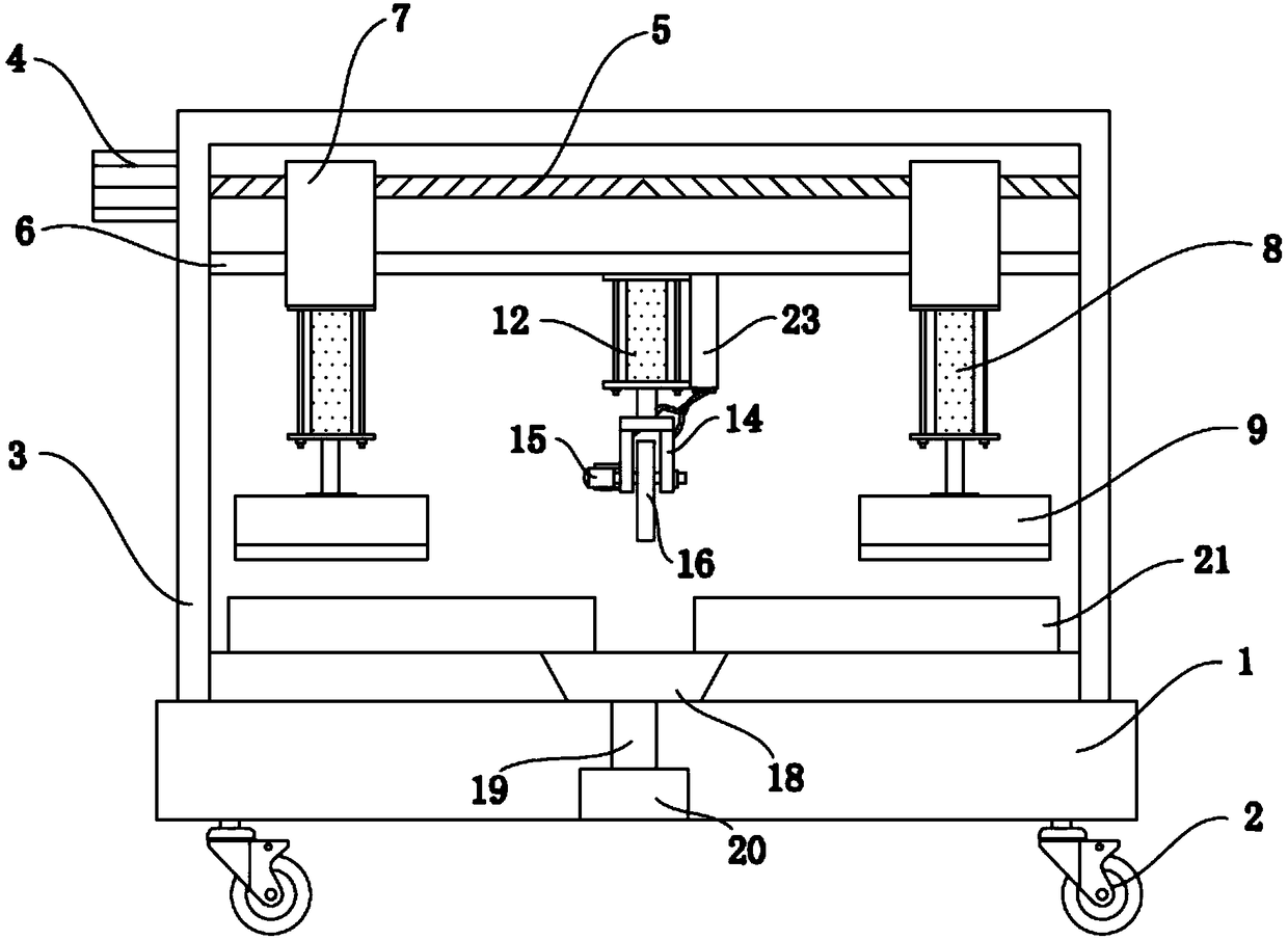
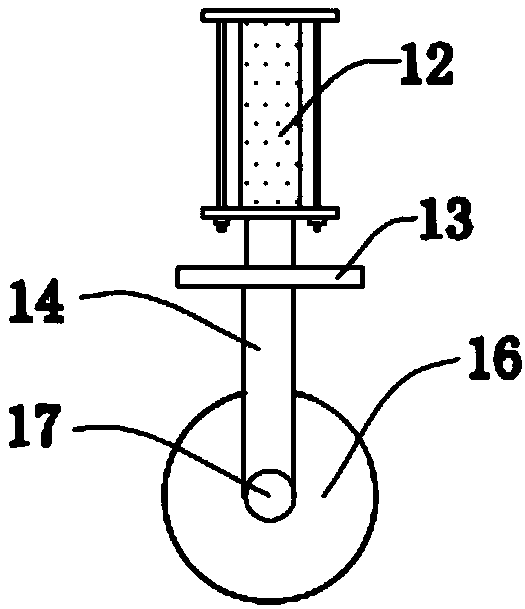
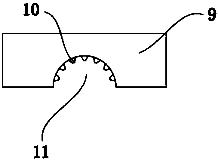
[0022] see Figure 1-6 , the present invention provides a technical solution: a cutting machine for construction machinery processing, including a dust collection room 1, a frame 3 is installed on the top of the dust collection room 1, and a The first motor 4, the output end of the first motor 4 is connected with a screw mandrel 5 through a shaft coupling, a guide rod 6 is provided directly below the screw mandrel 5, and a guide rod 6 runs through the guide ro...


PUM


Abstract

The invention discloses a cutting machine for mechanical processing of construction engineering, including a dust collecting chamber with a body frame on the top of the dust collecting chamber. A first motor is installed on the left side of the top of the body frame. The output end of the first motor is connected with a screw rod through a coupling. Two moving blocks are provided through the guiderod and screw rod, and the bottom of the two moving blocks are connected with a first hydraulic cylinder. The output end of the first hydraulic cylinder is connected with the compression block through the piston rod. Start the first hydraulic cylinder and drop so that the pressure nail is in close contact with the steel pipe to effectively prevent skidding, so as to greatly improve the clamping stability. Drop the second hydraulic cylinder by starting the second motor to, cut the steel pipe, Due to the fact that the high temperature may be caused by circular cutter during the cutting process,so a micro water pump and a valve on the first water pipe need to be start to make the water in the water tank spray through the jet hole to the circular cutter for cooling, which can greatly extendthe service life of the circular cutter.

Description

technical field [0001] The invention relates to the technical field of cutting machines, in particular to a cutting machine for mechanical processing of construction engineering. Background technique [0002] Construction engineering refers to engineering entities formed through the construction of various housing buildings and their ancillary facilities and the installation activities of supporting lines, pipelines, and equipment. As well as projects that can form internal spaces to meet the needs of people's production, living, learning, and public activities. When construction projects are in progress, cutting devices will be used to cut steel pipes. [0003] At present, the existing steel pipe cutting devices on the market can basically be cut by pressing down on the workers when they are in use, and cannot realize automatic cutting. This will make the cutting devices inconvenient to use, and the existing The cutting device does not have a device for cooling the cutter,...

Claims


Application Information

Patent Timeline
Patent Type & Authority Applications(China)
IPC IPC(8): B23D21/00B23Q3/08B23Q11/10
CPCB23D21/00B23Q3/064B23Q3/082B23Q11/10
Inventor 马晓娇李秀兰
Owner 淮北市腾威机械设备有限公司
Why Eureka
Try Eureka