Tar separation unit and tar separation system

A separation unit and separation system technology, applied in the field of annular tar separation unit and multi-stage tar separation system, tar separation unit and tar separation system, annular multi-stage tar separation unit and multi-stage tar separation system, can solve the problem that is difficult to adapt to large-scale Problems such as modernized projects, poor cooling effect, and large floor area, etc., to achieve the effect of improving cooling effect, reducing equipment volume, and improving cooling water utilization

Pending Publication Date: 2019-01-18
HUNAN YUANYANG COAL MACHINE MFG
View PDF0 Cites 2 Cited by
  • Summary
  • Abstract
  • Description
  • Claims
  • Application Information

AI Technical Summary

Problems solved by technology

However, this method mainly has poor cooling effect, and a large amount of water and tar are mixed to form secondary water pollution. In order to solve the above problems, a "multi-stage tar separator" has been publicized. This process adopts external cooling, and the gas and cooling water are separated. This solves the problem of water pollution and has the advantages of better cooling effect. However, due to the gradual development of waste pyrolysis and gasification technology projects in the market from small projects to large-scale projects, this single-tube arrangement and multi-stage decoking method is difficult to adapt to large-scale projects. , because the condensation method is used to decoke, the smaller the diameter of the cooling pipe, the better the cooling effect. The larger the diameter of the gas pipeline and the thinner multi-pipe arrangement of the cooling pipeline, the disadvantages are that the equipment is too large, the cost is high, and the floor area is large.

Method used


Image

  • Tar separation unit and tar separation system
  • Tar separation unit and tar separation system
  • Tar separation unit and tar separation system

Examples


Embodiment Construction

[0039] The present invention will be described in detail below in conjunction with examples. It should be noted that, in the case of no conflict, the embodiments of the present invention and the features in the embodiments can be combined with each other. For the convenience of description, if the words "up", "down", "left" and "right" appear in the following, it only means that the directions of up, down, left and right are consistent with the drawings themselves, and do not limit the structure.

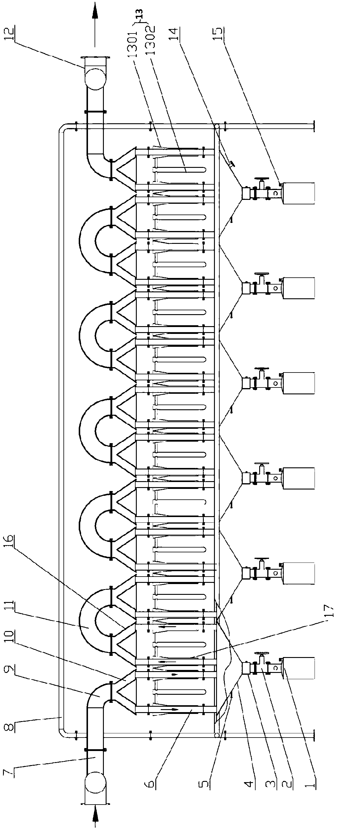
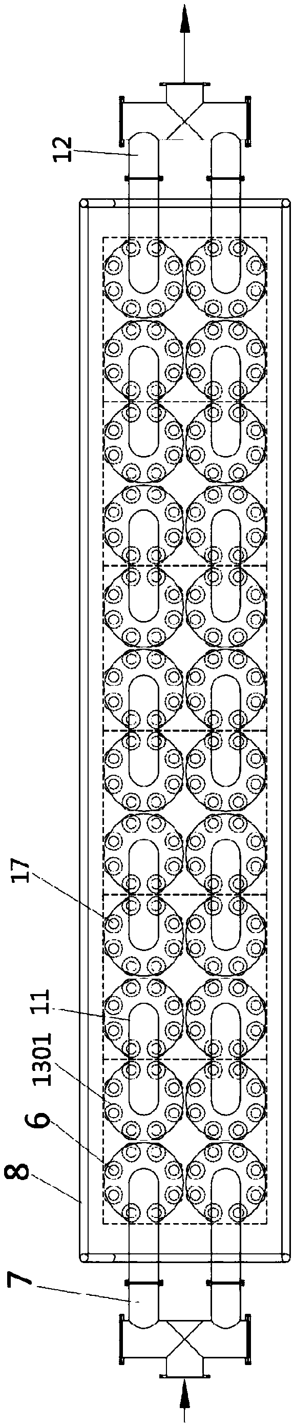
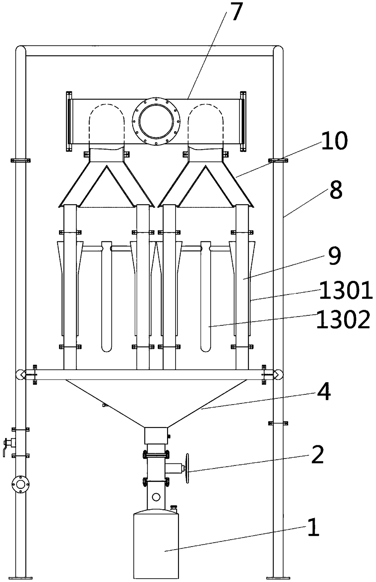
[0040] like Figure 1 to Figure 3As shown, a tar separation system includes a sequentially connected intake pipe 7, six tar separation units, and an outlet pipe 12; the tar separation unit shown includes a bucket 4, a first distributor 10 located above the bucket 4, and a second distributor 16, the first distributor 10 communicates with the bucket 4 through at least two first pipes 6, and the bucket 4 communicates with the second distributor 10 through at least two second pipes 17....


PUM


Abstract

The invention relates to a tar separation unit and a tar separation system. The tar separation unit comprises a hopper, a first distributor and a second distributor, wherein the first distributor andthe second distributor are located above the hopper, the first distributor is communicated with the hopper through two first pipes, the hopper is communicated with the second distributor through at least two second pipes, and cooling systems are arranged around the first pipes and the second pipes; and a bucket is communicated to the bottom of the hopper. The tar separation unit has a condensationseparation effect, tar components collected in each tar separation unit are relatively uniform; and the first pipe or the second pipe in the same tar separation unit are circumferentially distributed, the water supply of multiple first pipes can be finished only through a water supply pipe, so that the structure can be simplified.

Description

technical field [0001] The invention relates to the technical separation field of biomass, garbage, industrial organic waste and coal coking, and specifically relates to an annular multi-stage tar separation unit and a multi-stage tar separation system. [0002] The invention belongs to the fields of biomass pyrolysis gasification, garbage pyrolysis gasification, coal gasification, coking chemical gas purification and tar separation, and specifically relates to a tar separation unit and a tar separation system, in particular to an annular tar separation unit And multi-stage tar separation system. Background technique [0003] The pollution of garbage to the environment has been raised to the national agenda. According to the national document No. 227 in 2016, the four departments jointly issued the "Opinions on Further Strengthening the Incineration and Treatment of Municipal Domestic Waste", which fully reflects the country's emphasis on garbage disposal. Garbage is harmle...

Claims


Application Information

Patent Timeline
Patent Type & Authority Applications(China)
IPC IPC(8): C10C1/00B01D5/00
CPCC10C1/00B01D5/0003B01D5/0036B01D5/0054
Inventor 李本平李达阳芳南
Owner HUNAN YUANYANG COAL MACHINE MFG
Why Eureka
Try Eureka