Horizontal-type supporting method for foundation pit of arch shell

A technology of foundation pit support and arch shell foundation, which is applied in excavation, infrastructure engineering, construction, etc., can solve the problems of dense support spacing and low excavation efficiency, and achieves the advantages of easy quality, reduced excavation difficulty and cost saving. Effect

Inactive Publication Date: 2019-01-18
ANHUI URBAN CONSTR DESIGN & RES INST
View PDF8 Cites 5 Cited by
  • Summary
  • Abstract
  • Description
  • Claims
  • Application Information

AI Technical Summary

Problems solved by technology

[0006] The purpose of the present invention is to overcome the deficiencies of the prior art and provide a horizontal arch shell foundation pit support method to solve the technical problem of low excavation efficiency caused by dense support spacing in the prior art

Method used


Image

  • Horizontal-type supporting method for foundation pit of arch shell
  • Horizontal-type supporting method for foundation pit of arch shell
  • Horizontal-type supporting method for foundation pit of arch shell

Examples


Embodiment 2

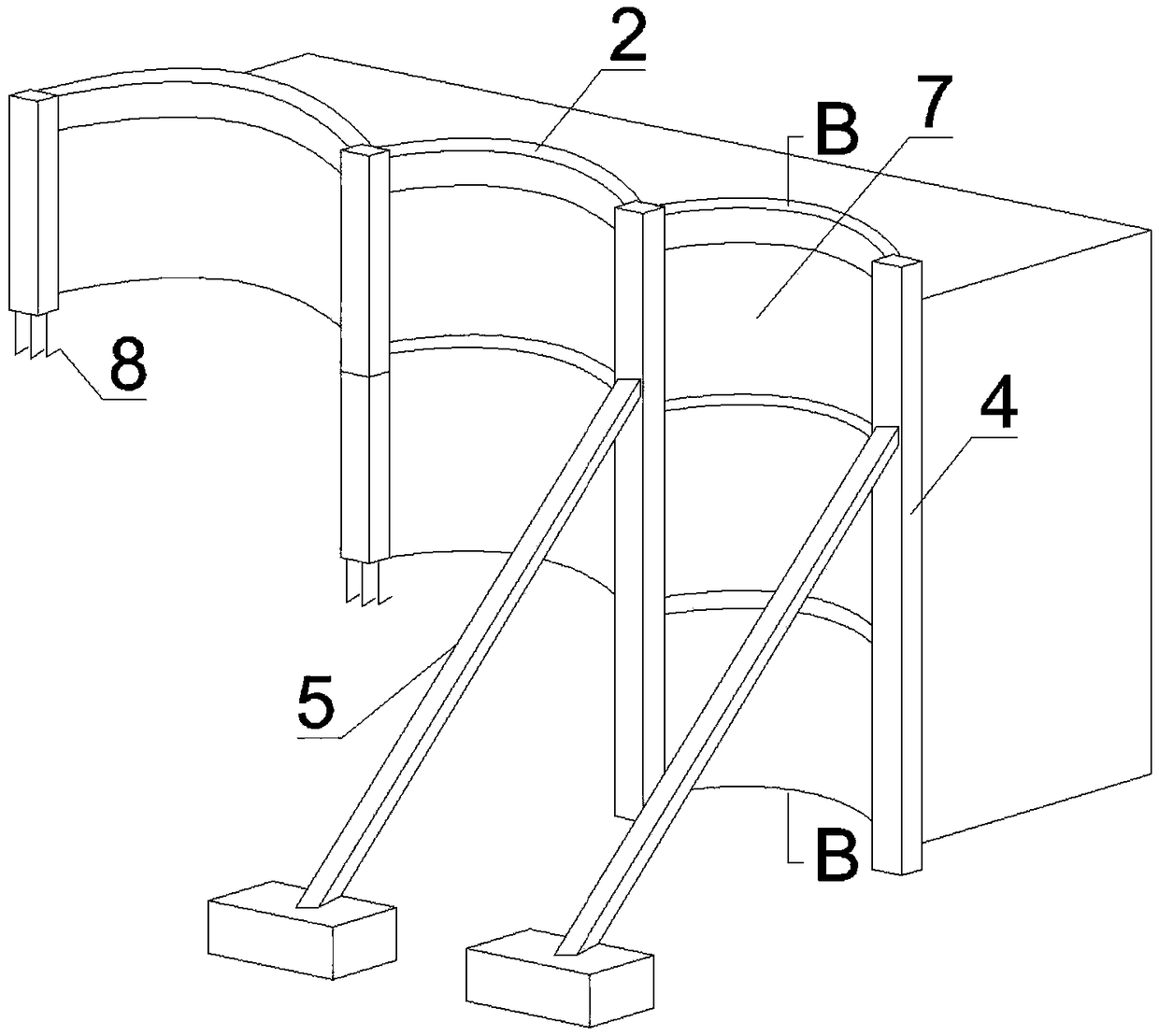
[0077] refer to image 3 and Figure 4 , the support method in this embodiment is similar to that in the first embodiment, the main difference is that the arch beam 3 in the first embodiment is replaced by a reinforced concrete upside-down arch slab 7 poured in layers from top to bottom. The head of the vertical anchor pipe 9 and the head of the horizontal anchor pipe 10 are all anchored in the corresponding upside-down arch 7 .

[0078] That is, the arch beam 3 constructed on each floor is replaced with an upside-down arch slab 7, so that the protective panel 6 can no longer be constructed. The thickness of the 7 floors of the upside-down arch slabs is greater than that of the upside-down arch slab 7 on the upper floor, which constitutes a downwardly extending ladder shape, which is helpful for construction. At the same time, it is equivalent to providing a gravity wall, which can effectively improve the foundation For the strength of the pit support, after the two ends of ...

Embodiment 3

[0081] In this embodiment, the construction steps are similar to Embodiment 1, the main difference is that the support assembly 5 has the original diagonal bracing replaced with a symmetrical During construction, it is only necessary to mirror the same support structure on both sides of the foundation pit with respect to the center of the foundation pit, and the whole pier 4 on both sides shares the same support assembly 5, so that the support structure can be greatly reduced. cost, and the support frame can be constructed synchronously after the construction pier of each excavation layer is completed. Reduce support costs.

[0082] It can be seen from the above examples that the horizontal arch shell foundation pit support method provided by the present invention has changed the disadvantages of using dense support in the traditional pile wall support, effectively improved the support span, and the arch shell type support The support structure can greatly improve the support...


PUM


Abstract

The invention discloses a horizontal-type supporting method for a foundation pit of an arch shell and relates to the field of foundation pit supporting. The method comprises the steps that a continuous wall column pile with an orthographic projection curve is constructed at the top of the side wall of the foundation pit, the curve is composed of arcs of multiple circle centers at the same side, and the adjacent ends of every two adjacent arcs are connected; after a corresponding pile top beam is constructed at the top of the wall column pile, multiple digging layers are dug, a corresponding arch rack beam or a corresponding protection panel is constructed on each digging layer, integral buttresses are constructed at the two corresponding ends of each arc, the two adjacent ends of every twoarcs share one integral buttress, a supporting assembly corresponding to each integral buttress is constructed again and effectively supported, and an advanced vertical anchor pipe and an advanced horizontal anchor pipe are constructed on each digging layer. According to the horizontal-type supporting method, the defects of dense supporting of a traditional row pile wall are overcome, the span among the supporting assemblies is increased, and the digging difficulty is lowered.

Description

technical field [0001] The invention relates to the technical field of geotechnical engineering, in particular to a support method combining a transverse arch shell and a support in a temporary foundation pit support method. Background technique [0002] At present, the domestically adopted pile-row internal support foundation pit support is to arrange the surrounding piles in a straight line along the periphery of the foundation pit, and arrange the internal support rods at almost equal intervals to form a fulcrum for the surrounding piles. The horizontal spacing of reinforced concrete supports is generally 7 to 12 meters, and the horizontal spacing of steel supports is generally 3 to 9 meters. The current technology has the following problems: [0003] 1. Earth excavation is difficult. Due to the dense support spacing, large-scale equipment cannot be used for excavation, and only small excavators can be used for excavation, which has low work efficiency and has a signific...

Claims


Application Information

Patent Timeline
Patent Type & Authority Applications(China)
IPC IPC(8): E02D17/04
CPCE02D17/04
Inventor 束冬青蔡敏李彪孟玉刘少凯吴东彪周阳李天宝张龙飞刘贵强单灿灿孙昌兴郑永磊
Owner ANHUI URBAN CONSTR DESIGN & RES INST
Why Eureka
Try Eureka