Tunneling machine cutting trace planning system and method

A trajectory planning and roadheader technology, which is applied to earthwork drilling, slitting machinery, computer parts, etc., can solve problems such as deviations, analysis results errors, and limitations during the excavation process, so as to avoid detonating gas at dangerous temperatures and improve System response time, effects of avoiding wear and damage

Active Publication Date: 2019-01-18
CHINA UNIV OF MINING & TECH
View PDF8 Cites 3 Cited by
  • Summary
  • Abstract
  • Description
  • Claims
  • Application Information

AI Technical Summary

Problems solved by technology

This path planning method can be roughly divided into two types, one is global path planning based on complete environmental prior information, also known as static or offline planning; the other is local path planning based on sensor information, also known as The disadvantage of dynamic or online path planning, static or offline planning is that it cannot feed back the underground environment in real time, and its adaptability is poor. For coal mining faces with poor geological conditions, this method is severely limited, and its accuracy depends on the operation Due to the working experience of the personnel, the operator needs to judge the coal-rock interface and gangue and adjust the cutting path based on the experience. There is a lag, and the excavation process is prone to deviation; while the local planning path based on multi-sensor information needs to design multi-sensor parameters. The change of rock hardness is described, but the obtained description information is not comprehensive, which may easily lead to errors in path planning, and in the process of information integration, it is necessary to analyze the parameters of multiple sensors. When a sensor is damaged, the feedback information will be incomplete. , resulting in errors in the analysis results

Method used


Image

  • Tunneling machine cutting trace planning system and method
  • Tunneling machine cutting trace planning system and method
  • Tunneling machine cutting trace planning system and method

Examples


Embodiment Construction

[0032] The present invention will be described in detail below in conjunction with the accompanying drawings.

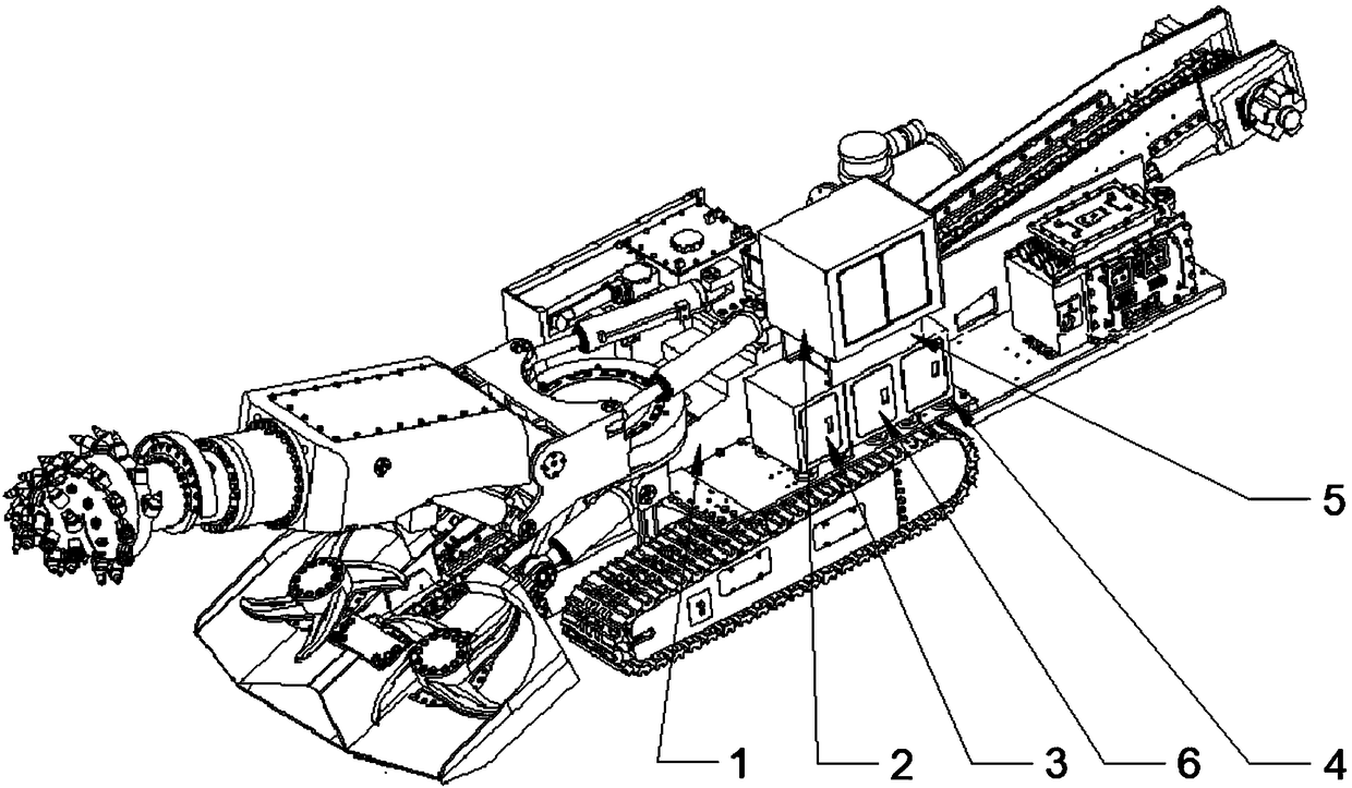
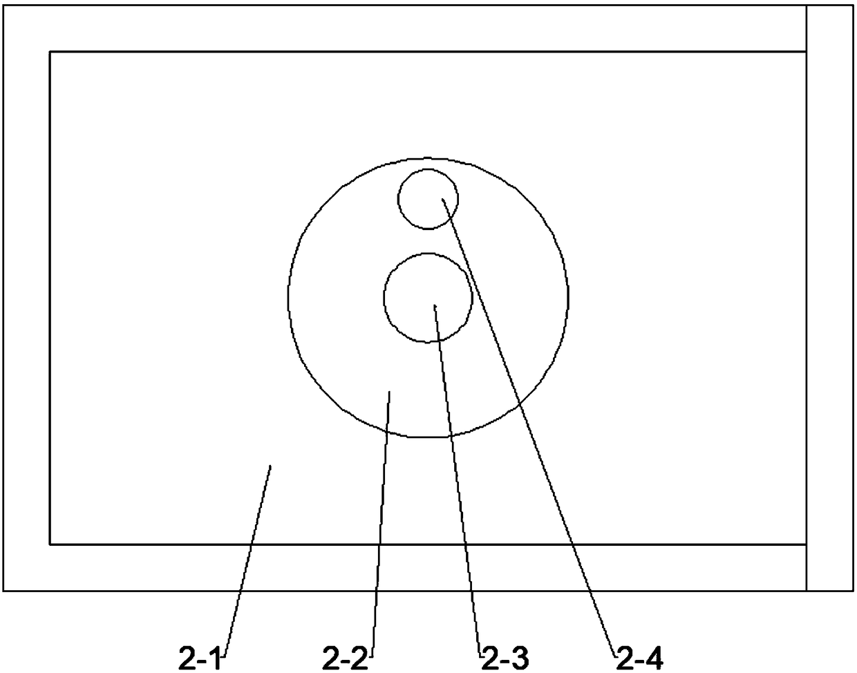
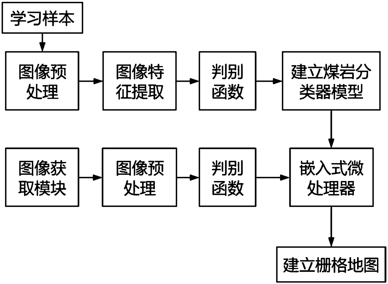
[0033] Such as Figure 1 to Figure 3 As shown, a roadheader cutting track planning system is characterized in that it includes an image acquisition module 2, a data processing module 3 and a control module 6 installed on the roadheader main body 1; the image processing module 2 includes an explosion-proof housing 2-1 and the CCD camera 2-3 installed in the explosion-proof housing, the explosion-proof housing at the front end of the camera 2-3 of the CCD is provided with a high light transmission window 2-2, and the top of the CCD camera 2-3 is equipped with a flameproof Searchlight 2-4; Described data processing module 3 comprises embedded microprocessor system and PLC control system, and CCD camera 2-3 sends the image information of shooting to microprocessor system, and microprocessor system uses the information after processing as input The variable signal is sen...


PUM


Abstract

The invention discloses a tunneling machine cutting trace planning system and method. The system comprises an image acquisition module, a data processing module and a control module, wherein the imageacquisition module, the data processing module and the control module are mounted on a tunneling machine main body. The trace planning method comprises the following steps: modeling on the basis of an orthohexagonal grid method, and dividing an area to be cut into a plurality of orthohexagonal grid units of an identical size with binary value information; dividing an ideal area into a plurality of free area units which are overlapped with one another by using a unit division method with obstacles as boundaries, and representing transferring of one area unit to another area with adjacent images; calculating planning of an optimal route by using an algorithm. By adopting the system, a tunneling machine cutting head can automatically avoid dirt bands in the tunnel cutting process, cutting tooth abrasion can be reduced, the service life of each cutting tooth can be prolonged, the cutting speed can be increased, the cutting efficiency can be improved, and conditions are provided for automatic and efficient operation of a tunneling machine.

Description

technical field [0001] The invention relates to a roadheader, in particular to a cutting track planning system and method of the roadheader, and belongs to the technical field of underground roadheading equipment. Background technique [0002] Coal mine roadway excavation is an important process in the process of coal mining, and the speed of coal mine roadway excavation will directly affect the efficiency of coal mining. In recent years, with the development of China's coal mine technology, although coal mine roadway excavation technology and equipment have achieved rapid development, due to the complex occurrence conditions of coal resources in China, roadway excavation technology and equipment are still important factors restricting the high production and efficiency of coal mining. The development of fully mechanized excavation is far behind that of fully mechanized mining. High-efficiency mechanized excavation is a necessary condition to ensure high production and high ...

Claims


Application Information

Patent Timeline
Patent Type & Authority Applications(China)
IPC IPC(8): E21C35/24E21C31/08G06K9/62
CPCE21C31/08E21C35/24G06F18/2411
Inventor 刘送永朱真才贾新庆江红祥吴洪状沈刚彭玉兴周公博周达张德义
Owner CHINA UNIV OF MINING & TECH
Why Eureka
Try Eureka