Accumulated piezoelectric-solenoid double-valve electronically controlled fuel injector

An electronically controlled fuel injection and pressure storage technology, which is applied in fuel injection devices, machines/engines, charging systems, etc., can solve problems such as abnormal operation, pressure fluctuations, and adverse consequences, and achieve reduced oil return and reliable The effect of high performance and improved response speed

Active Publication Date: 2020-12-29
HARBIN ENG UNIV
View PDF5 Cites 0 Cited by
  • Summary
  • Abstract
  • Description
  • Claims
  • Application Information

AI Technical Summary

Problems solved by technology

[0003] The electronically controlled fuel injector is the core component of the high-pressure common rail fuel system of the diesel engine. It overcomes the problem that the fuel injection law of the mechanical fuel injector is restricted by the shape of the cam, and realizes the flexible and controllable fuel injection rate. The pressure-type electronically controlled fuel injector can further pressurize the high-pressure fuel in the common rail pipe to obtain higher injection pressure, but it is easy to cause large pressure fluctuations in the working process, and for the booster controlled by a single valve As far as the pressure type fuel injector is concerned, once the solenoid valve fails, the entire fuel injector will not work normally, which will easily cause adverse consequences.

Method used


Image

  • Accumulated piezoelectric-solenoid double-valve electronically controlled fuel injector
  • Accumulated piezoelectric-solenoid double-valve electronically controlled fuel injector
  • Accumulated piezoelectric-solenoid double-valve electronically controlled fuel injector

Examples


Embodiment Construction

[0021] The present invention will be described in more detail below in conjunction with the accompanying drawings:

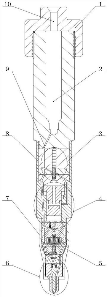
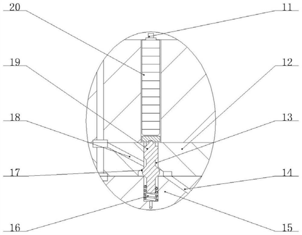
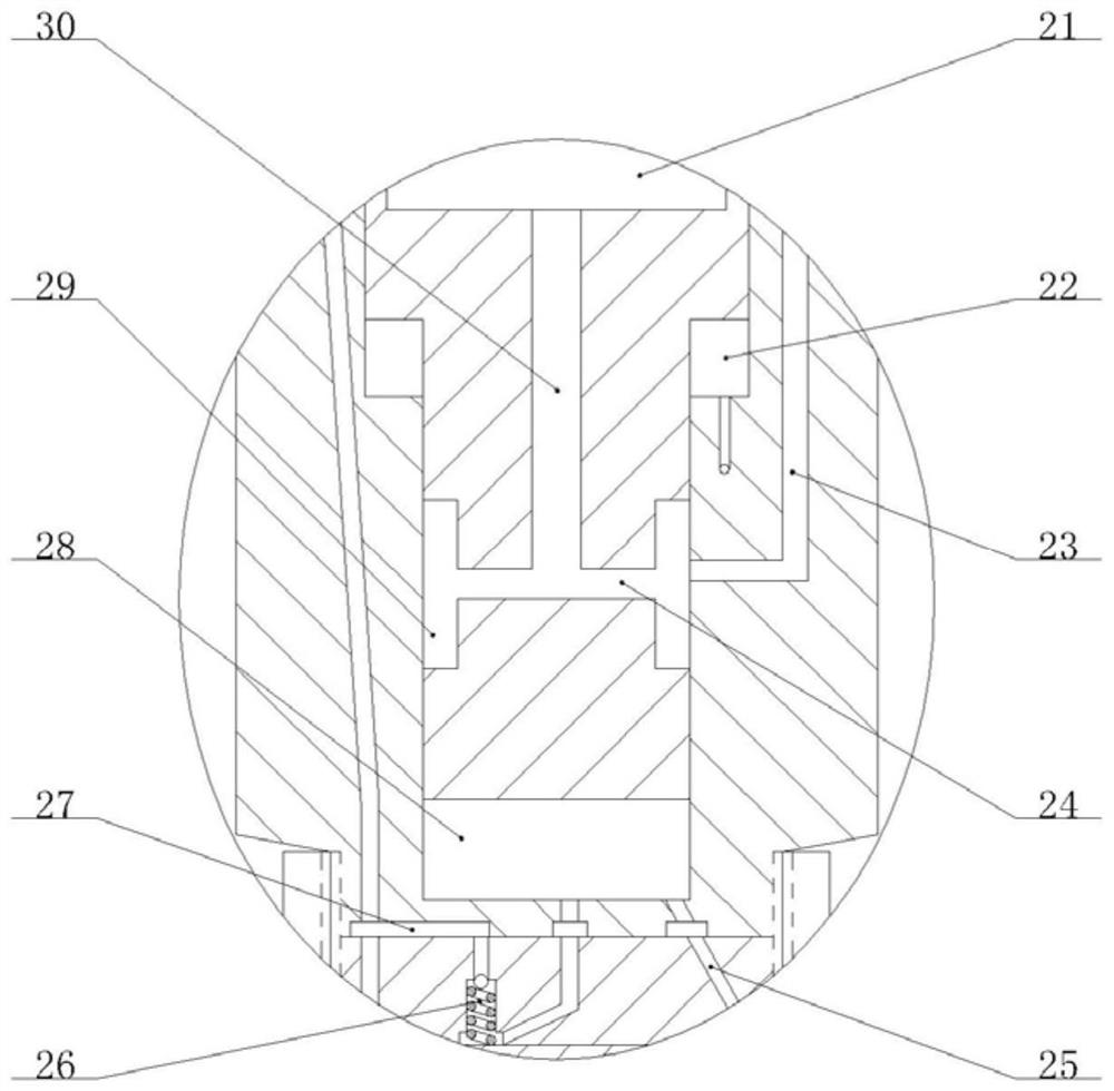
[0022] combine Figure 1-5 , The pressure accumulating piezoelectric-electromagnetic double valve electronically controlled fuel injector of the present invention includes an injector head 1, a pressure accumulating chamber 2, a booster control valve 3, a booster piston 4, an fuel injection control valve 5, and a nozzle 6 , tight cap 7 and injector body 8, the injector head 1 is installed on the injector body 8, the fuel injector body 8 is provided with a pressure accumulating cavity 2, and the injector head 1 is provided with a main oil inlet hole 10. The main oil inlet hole 10 is communicated with the upper end of the accumulator chamber 2, the lower end of the accumulator chamber 2 is communicated with the main oil inlet circuit 9, the booster control valve 3, booster piston 4, fuel injection control valve 5 and nozzle 6 are from top to bottom. The lower par...


PUM


Abstract

It is an object of the present invention to provide a pressure-accumulating piezoelectric-electromagnetic dual-valve electronic fuel injector which comprises a pressurizing control valve, a pressurizing piston, a fuel injection control valve, a nozzle and a fuel injector body. The fuel injector body is provided therein with a pressure-accumulating chamber, which can reduce the pressure fluctuationin a fuel injection process, and is advantageous for the precise control of the fuel injection. A piezoelectric stack and the electromagnetic valves can be configured to independently control the pressurization process and the fuel injection process such that the pressure-accumulating piezoelectric-electromagnetic dual-valve electronic fuel injector can work in both non-pressurizing and pressurizing modes. In the non-pressurizing mode, the rail pressure injection is performed. In the pressurizing mode, the ultrahigh-pressure injection is performed, and the pressuring ratio can be flexibly adjusted, thereby achieving high reliability and a wide application range. The fuel injection control valve can stop the control chamber from replenishing the fuel during the fuel draining process, realizes micro dynamic oil return, improves the response speed of the needle valve, and improves the dynamic property and economical efficiency of a diesel engine.

Description

technical field [0001] The invention relates to a fuel system, in particular to a marine diesel engine fuel system. Background technique [0002] The diesel electronically controlled high pressure common rail fuel system can optimize the performance of the diesel engine under different working conditions by precisely controlling the parameters such as fuel injection pressure, fuel injection quantity and fuel injection timing, which is an inevitable trend of diesel engine development in the future. With the increasing number of diesel engines, people pay more and more attention to the fuel economy and emission performance, so the improvement of diesel engine fuel system has received much attention. [0003] The electronically controlled injector is the core component of the high-pressure common rail fuel system of the diesel engine. It overcomes the problem that the fuel injection rule of the mechanical injector is restricted by the shape of the cam, and realizes the flexibil...

Claims


Application Information

Patent Timeline
Patent Type & Authority Patents(China)
IPC IPC(8): F02M51/06F02M47/02F02M61/10F02M61/16F02M61/18F02M63/00
CPCF02M47/027F02M51/0603F02M51/061F02M61/10F02M61/16F02M61/18F02M63/0017F02M63/0026
Inventor 白云兰奇范立云马修真
Owner HARBIN ENG UNIV
Why Eureka
Try Eureka