
A high-efficiency wave energy generating device

A technology of power generation device and wave energy, applied in ocean energy power generation, engine components, machines/engines, etc., can solve the reliability problems of wave energy conversion devices, restrict the commercial development of wave energy utilization, and have complex structures of wave energy conversion devices, etc. problems, to achieve the effect of improving ease of maintenance, reducing load, and ensuring reliability

Inactive Publication Date: 2020-12-22
北京驭海能源技术中心(有限合伙)
View PDF5 Cites 0 Cited by
  • Summary
  • Abstract
  • Description
  • Claims
  • Application Information

AI Technical Summary

Problems solved by technology

The conversion efficiency of the existing wave energy conversion device is limited, and the reliability of the operation of the existing wave energy conversion device is not high; Sexual issues have always restricted the commercial development of wave energy utilization

Method used


Image

  • A high-efficiency wave energy generating device
  • A high-efficiency wave energy generating device
  • A high-efficiency wave energy generating device

Examples


Embodiment 1

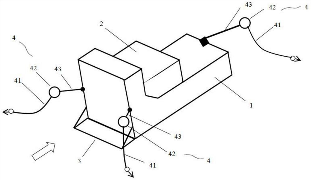
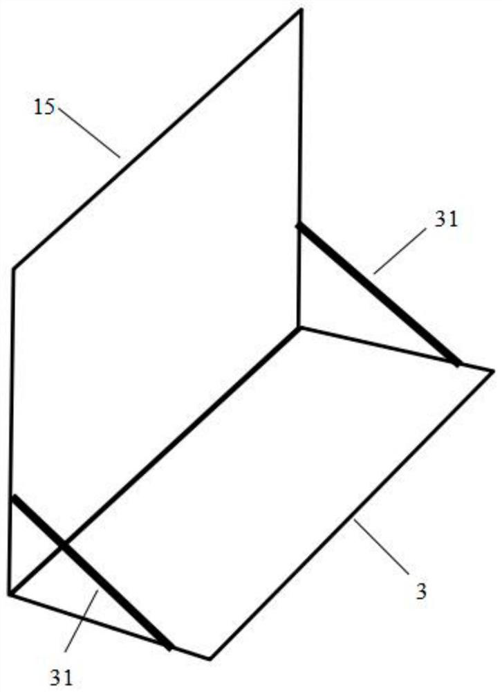
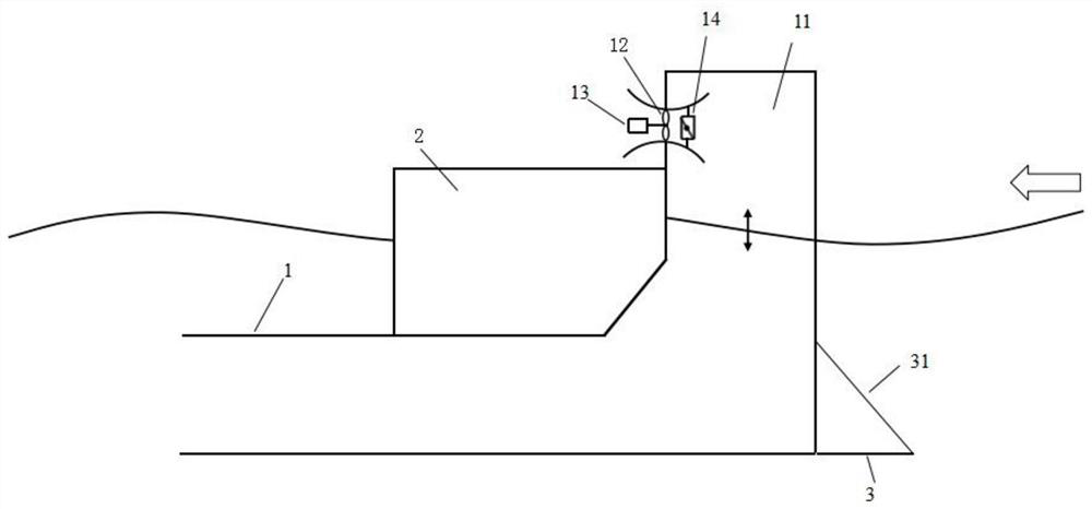
[0029] Such as Figure 1-5 As shown, the high-efficiency wave energy power generation device of this embodiment includes a buoyancy tank 2, an air turbine 12, a mooring system 4, an L-shaped water body conduit 1 and a horizontal pressure water plate 3, and the water body conduit 1 includes a vertical portion and a horizontal portion. One end of the horizontal part communicates with the bottom end of the vertical part, and the height of the vertical part is the same as that of the water conduit 1; the buoyancy tank 2 is arranged at the angle between the vertical part and the horizontal part, and the top of the vertical part is closed , Two ventilation holes are arranged on the side wall of the vertical part; chamfers are provided at the angle between the vertical part of the water body conduit 1 and the horizontal part of the water body conduit 1 .

[0030] refer to Figure 4 and Figure 5, the air turbine 12 in this embodiment includes a first air turbine 121 and a second ai...

Embodiment 2

[0036] Such as Figure 6-7 As shown, the high-efficiency wave energy power generation device of this embodiment is basically the same in structure as the high-efficiency wave energy power generation device of the above-mentioned embodiment 1, and the difference lies in:

[0037] The high-efficiency wave energy generating device of this embodiment also includes an auxiliary buoyant tank 21 arranged between the vertical part of the water body conduit 1 and the pressure water plate 3, the height of the auxiliary buoyancy tank 21 is equal to the height of the water body conduit 1, and the water pressure plate 3 One end of one end is connected with the bottom of auxiliary floating tank 21, and the other end of pressure water plate 3 is fixedly connected with the side wall of auxiliary floating tank 21 by inclined rod 31. The high-efficiency wave energy generating device of this embodiment adopts the double buoyant design of the buoyancy tank 2 and the auxiliary buoyancy tank 21, an...


PUM


Abstract

The invention discloses a high-efficiency wave energy power generation device, which includes a buoyancy tank, an air turbine, a mooring system, an L-shaped water body conduit and a horizontal pressure water plate, the water body conduit includes a vertical part and a horizontal part, and one end of the horizontal part It communicates with the bottom of the vertical part, and the height of the vertical part is the same as that of the water body conduit; the buoyant tank is arranged at the angle between the vertical part and the horizontal part, the top of the vertical part is closed, and the side wall of the vertical part There is a ventilation hole, the air turbine is arranged at the ventilation hole, the outer wall of the air turbine is sealed and connected with the ventilation hole, and the air turbine is provided with a control valve for opening and closing the air flow channel of the air turbine, and the air turbine and The generator set is connected, one side of the pressure water plate is fixedly connected with the bottom end of the front outer wall of the vertical part, and the other side of the pressure water plate is fixedly connected with the front outer wall of the vertical part through a diagonal rod; one end of the mooring system is fixed with the water body conduit The other end is anchored to the seabed. The high-efficiency wave energy generating device of the invention improves the conversion efficiency of wave energy.

Description

technical field [0001] The invention relates to the technical field of electric power equipment, in particular to a high-efficiency wave energy generating device. Background technique [0002] With the fossil energy crisis, environmental pollution and global warming caused by excessive carbon emissions, the demand for green and renewable energy is increasing. Wave energy is a clean renewable energy with the largest energy flow density, the widest distribution and the highest grade in ocean energy. Therefore, it is the focus of ocean energy research and development in various countries. Its development and utilization will help alleviate energy crisis and environmental problems. In particular, there are many islands and offshore platforms in our country. It is very urgent and important to provide power guarantee for normal production and living activities on the islands and offshore platforms. However, the islands and offshore platforms are far away from the mainland. It is v...

Claims


Application Information

Patent Timeline
Patent Type & Authority Patents(China)
IPC IPC(8): F03B13/24
CPCF03B13/24Y02E10/30F03B13/142
Inventor 盛万安
Owner 北京驭海能源技术中心(有限合伙)
Learn More