
Rebound valve plate and damper valve system

A technology for stretching valves and shock absorbers, applied in the direction of shock absorbers, springs/shock absorbers, shock absorbers, etc., can solve problems affecting ride comfort, damping force reduction, and affecting vehicle handling, etc., to improve Ride comfort and handling stability, the effect of constant damping force

Pending Publication Date: 2019-01-18
SHANGHAI BAOLONG AUTOMOTIVE CORP +1
View PDF7 Cites 2 Cited by
  • Summary
  • Abstract
  • Description
  • Claims
  • Application Information

AI Technical Summary

Problems solved by technology

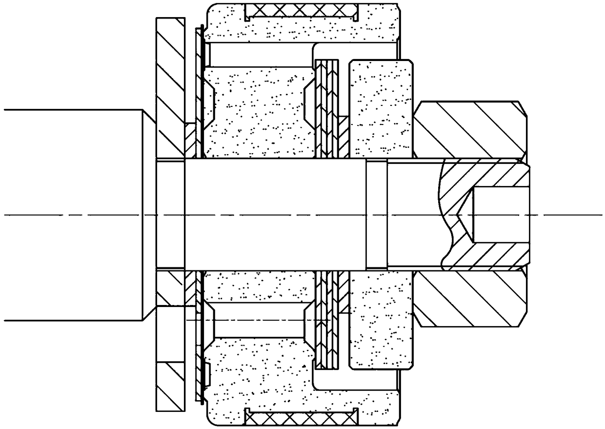
[0003] The factors affecting the damping force of the shock absorber include the shock absorber oil and the internal valve system. The temperature, viscosity and flow of the shock absorber oil have a linear relationship with the damping force. The temperature affects the viscosity. When the temperature and viscosity are constant, the flow rate It directly affects the damping force inside the shock absorber, and the amount of flow is controlled by the valve plate; refer to figure 1 , the traditional piston valve adopts the structure of valve plates and springs. Several valve plates are combined and stacked together. The material is the same carbon steel. Drive models are especially high-end cars that have strict requirements on comfort. In addition, the temperature difference between summer and winter is very large. In summer, due to the high temperature, the viscosity of the oil inside the shock absorber decreases, resulting in a decrease in damping force—the body is soft; on the contrary, The body is hard in winter, no matter what the situation is, it will affect the handling of the vehicle and thus affect the ride comfort

Method used


Image

  • Rebound valve plate and damper valve system
  • Rebound valve plate and damper valve system
  • Rebound valve plate and damper valve system

Examples


Embodiment Construction

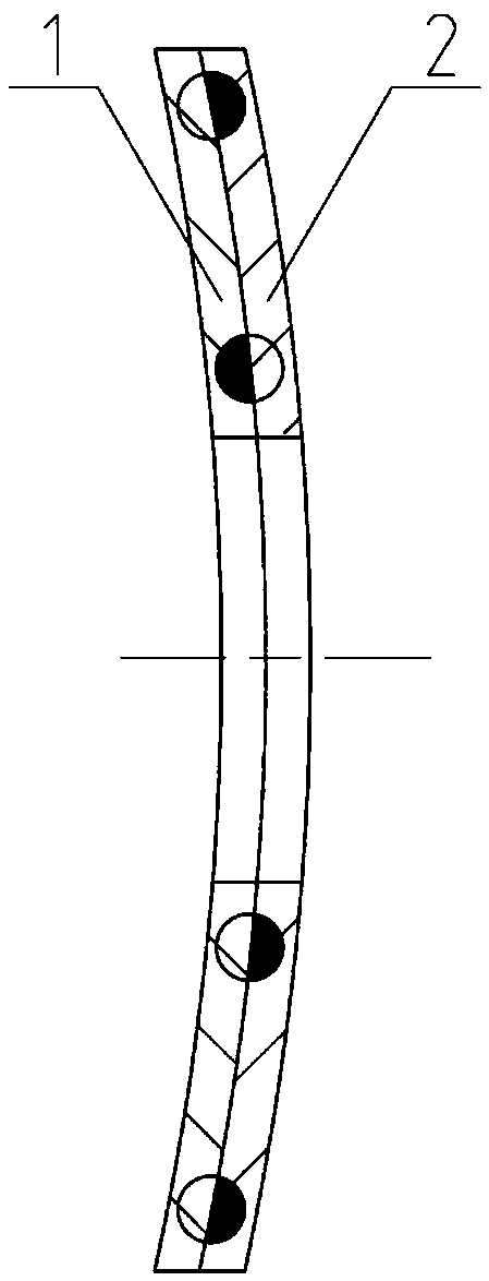
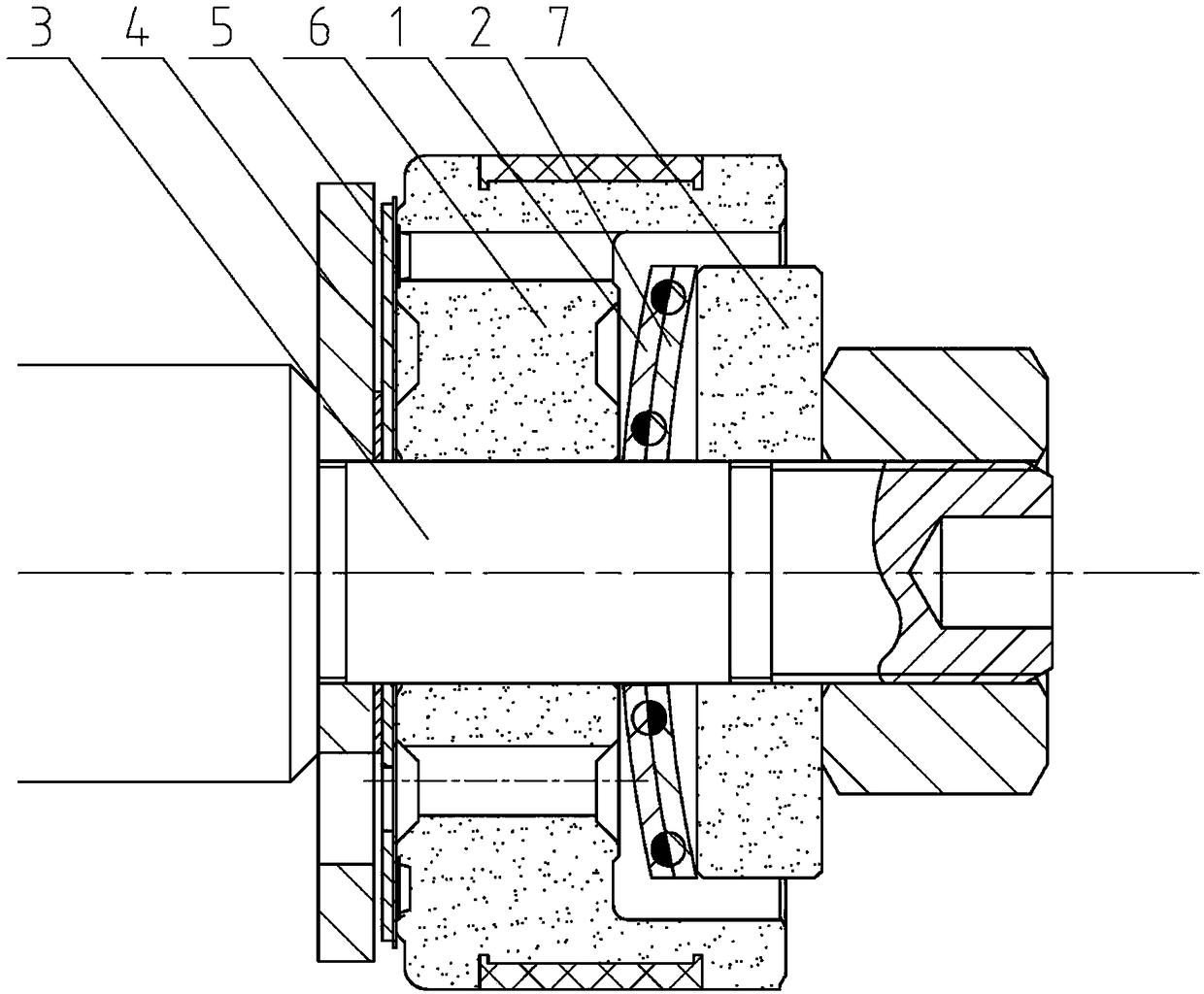
[0015] Such as Figure 1-3 as shown, figure 1 It is a structural schematic diagram of the shock absorber valve system in the prior art, figure 2 When the temperature is higher than room temperature, a schematic diagram of the structure of a stretched valve plate proposed by the present invention, image 3 It is a structural schematic diagram of a shock absorber valve system proposed by the present invention when the temperature is lower than room temperature.

[0016] refer to figure 2 , the present invention proposes a stretched valve plate, including a first valve plate part 1 and a second valve plate part 2, the first valve plate part 1 and the second valve plate part 2 are fixedly connected, and the thermal expansion coefficient of the first valve plate part 1 is is α1, the thermal expansion coefficient of the second valve plate part 2 is α2, and α1≠α2.

[0017] In this embodiment, the first valve section 1 is made of carbon steel material, the second valve section 2...


PUM


Abstract

The invention discloses a rebound valve plate. A first valve plate part is fixedly connected with a second valve plate part, the thermal expansion coefficient of the first valve plate part is alpha 1,the thermal expansion coefficient of the second valve plate part is alpha 2, and alpha 1 is not equal to alpha 2. The invention further discloses a damper valve system applying the rebound valve plate. As the working temperature rises, the viscosity of oil liquid is reduced, the rebound valve plate is arced towards the second valve plate part, the force of squeezing a piston valve body by the rebound valve plate is gradually reduced, so that a throttling valve plate moves towards the piston valve body along a connecting rod, a gap between the throttling valve plate and the piston valve body is reduced, then the flow passing through the gap is kept unchanged, and it is ensured that the damping force is constant; on the contrary, when the working temperature falls, the viscosity of the oilliquid is increased, the rebound valve plate is arced towards the first valve plate part, the rebound valve plate squeezes the piston valve body, so that the throttling valve plate moves towards a first limiting plate along the connecting rod, the gap between the throttling valve plate and the piston valve body is enlarged, then the flow passing through the gap is kept unchanged, and it is ensuredthat damping force is constant.

Description

technical field [0001] The invention relates to the technical field of a shock absorber valve system, in particular to an expansion valve plate and a shock absorber valve system. Background technique [0002] With the improvement of customers' requirements for automobile performance, especially the requirements for ride comfort, the requirements for shock absorption performance are also increasing. The impact of shock absorbers on comfort is a relatively large aspect, and the factors that affect the performance of shock absorbers There are many aspects. The piston valve system is the most important part for the shock absorber to generate damping force when the suspension spring is stretched and restored. According to different road conditions and speeds, the shock absorber must give different but appropriate damping matching. , to achieve ride comfort and operational stability. [0003] The factors affecting the damping force of the shock absorber include the shock absorber...

Claims


Application Information

Patent Timeline
Patent Type & Authority Applications(China)
IPC IPC(8): F16F9/34
CPCF16F9/34
Inventor 王胜全王贤勇陈敬辉万建波黄建松黄林辉
Owner SHANGHAI BAOLONG AUTOMOTIVE CORP
Learn More