Automatic guide method for measuring micro hole

An automatic guidance and round hole technology, applied in the field of image processing, can solve the problems of low degree of automation, low measurement efficiency, and difficulty in completing guidance operations, etc.

Active Publication Date: 2019-01-18
合肥庐阳科技创新集团有限公司
View PDF4 Cites 9 Cited by
  • Summary
  • Abstract
  • Description
  • Claims
  • Application Information

AI Technical Summary

Problems solved by technology

However, when using a contact probe for measurement, it is necessary to place the probe at the top of the probe into the circular hole. Since the diameter of the circular hole is only slightly larger than the diameter of the probe, it is difficult to complete the guiding operation with ...

Method used


Image

  • Automatic guide method for measuring micro hole
  • Automatic guide method for measuring micro hole
  • Automatic guide method for measuring micro hole

Examples


Embodiment Construction

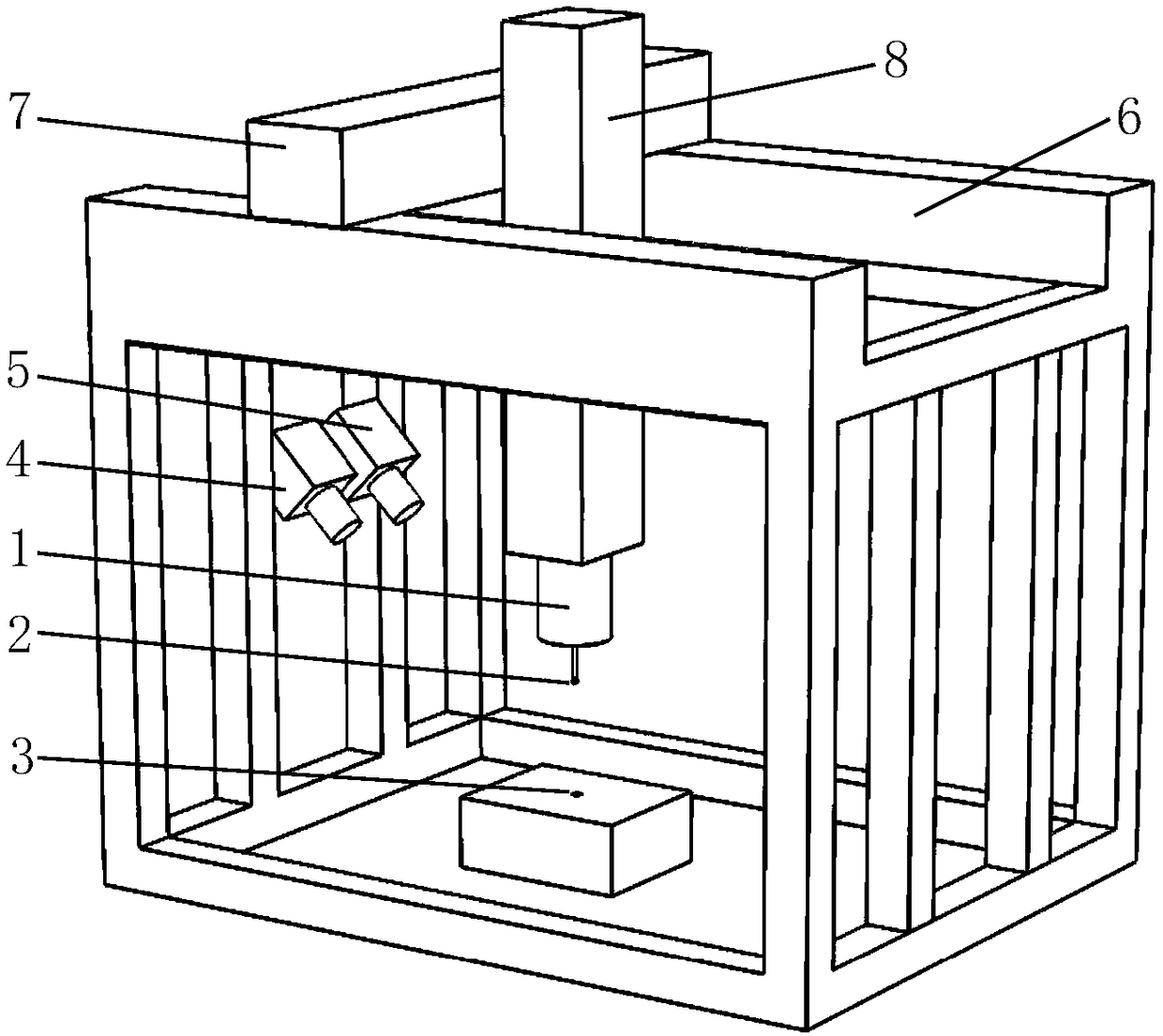
[0040] see figure 2 , in the present embodiment, the measurement of the miniature circular hole refers to adopting a three-coordinate measuring machine, and utilizing the probe 2 at the front end of the contact-type measuring probe to probe into the circular hole 3 to be measured for micro-hole measurement; the three-coordinate measuring machine consists of a base, X Axis 6, Y-axis 7 and Z-axis 8 are fixed on the base of one side of the three-coordinate measuring machine. Left camera 4 and right camera 5 with the same model and parallel optical axes are fixed. On the Z-axis 8 of the measuring machine, a spherical probe 2 is installed on the top of the contact measuring probe 1, and the probe 2 and the round hole 3 to be measured are both in the field of view of the left camera 4 and the right camera 5, where the camera The captured images are all in units of pixels, and the coordinate system is established with the vertex in the upper left corner of the image as the origin. T...


PUM


Abstract

The invention discloses an automatic guide method for measuring a micro hole. A left camera and a right camera are used for shooting a probe and a hole to be measured to acquire a left source figure and a right source figure, and an image A and an image B are generated via edge extraction; and oval detection is separately performed on the image A and the image B to acquire oval outlines of the probe and the hole in each image. Four envelop rectangles are acquired according to the four ovals, the images of the probes and holes in the left source figure and the right source figure are captured according to the four envelop rectangles and amplified to generate four images to perform edge extraction, edge points on the outermost layer are reserved to acquire four oval center coordinates, accordingly, the coordinates of the probes and the centers of the holes to be measured in the left source figure and the right source figure are acquired, and at last, the three-dimensional distance between the probe and the center of the micro hole to be measured is acquired by using a calibrated camera parameter, and a three-coordinate measurement machine is driven to complete guidance. According tothe method provided by the invention, the automatic guidance of the probe to the center of the micro hole is achieved, and the measurement efficiency of the micro hole can be greatly improved.

Description

technical field [0001] The invention relates to the field of image processing, in particular to an automatic guidance method suitable for measuring with a three-coordinate measuring machine and using a contact probe to measure miniature round holes. Background technique [0002] With the development of micro-nano technology, scientific instruments are developing toward precision, and parts are developing toward miniaturization, among which round holes are widely used in parts. However, it is very difficult to process micro-round holes, especially those with a diameter of less than 1 mm, such as oil pumps, oil nozzles and abrasive tools. Therefore, how to accurately detect the processing quality and related parameters of the micro-round hole is an important technical problem. [0003] In recent years, researchers have used structured light, laser interference, and laser triangulation to measure relevant parameters of micro-round holes. However, these measurement methods are ...

Claims


Application Information

Patent Timeline
IPC IPC(8): G01B5/008G01B21/04G01B11/14G06T7/13G06T7/62G06T7/70
CPCG01B5/008G01B11/14G01B21/047G06T7/13G06T7/62G06T7/70G06T2207/10004G06T2207/10056
Inventor 李瑞君李琪陶盼范光照
Owner 合肥庐阳科技创新集团有限公司
Why Eureka
Try Eureka