
A Speed ​​Planning Method for Picking and Placeing Components by Nozzles of Chip Mounter

A speed planning, placement machine technology, applied in the direction of electric speed/acceleration control, etc., can solve problems such as motor out-of-step and stall

Active Publication Date: 2021-05-18
ZHEJIANG UNIV OF TECH
View PDF7 Cites 0 Cited by
  • Summary
  • Abstract
  • Description
  • Claims
  • Application Information

AI Technical Summary

Problems solved by technology

[0004] In order to increase the speed during the pick-up and discharge movement of the suction nozzle of the existing placement machine, in order to overcome the influence of the component placement angle due to vibration during the rapid start and stop of the machine, and the motor head load due to high acceleration and deceleration And cause the problem of out-of-step stalling, the present invention provides a method that can realize the smooth start and stop of the stepping motor, speed up quickly, increase the maximum speed of the stepping motor, effectively avoid out-of-step and improve stability due to rapid acceleration to the highest speed. A revolutionary planning method for the speed planning of picking and placing components by the suction nozzle of the intelligent placement machine

Method used

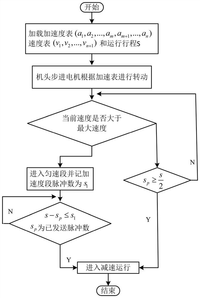
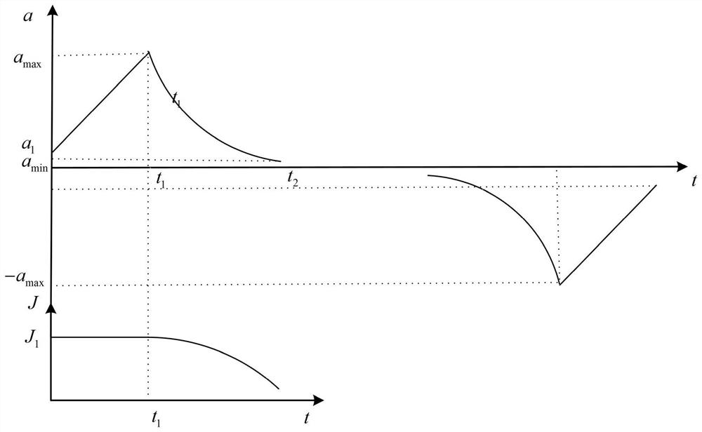
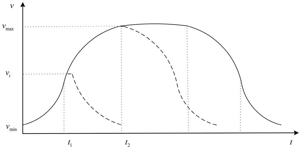

Image

  • A Speed ​​Planning Method for Picking and Placeing Components by Nozzles of Chip Mounter
  • A Speed ​​Planning Method for Picking and Placeing Components by Nozzles of Chip Mounter
  • A Speed ​​Planning Method for Picking and Placeing Components by Nozzles of Chip Mounter

Examples


Embodiment Construction

[0021] Embodiments of the present invention will be further described below in conjunction with the accompanying drawings.

[0022] refer to figure 1 , figure 2 and image 3 , a speed planning method for pick-and-place components of a head nozzle of a placement machine, said method comprising the following steps:

[0023] 1) In order to enable the head of the placement machine to start and stop more smoothly and accelerate to the maximum speed smoothly, an S-type acceleration mode is designed, in which, in the low-speed stage of the head running, the jerk J is maintained 1 constant, the acceleration movement with uniform acceleration increases, and the acceleration movement with reduced jerk is adopted during the high-speed acceleration stage of the nose, that is, the acceleration and deceleration sections of the acceleration curve are asymmetrical;

[0024] 2) According to the mechanical structure of the head nozzle of the placement machine, the suction force of the air p...


PUM


Abstract

A speed planning method for pick-and-place components by the head nozzle of a chip mounter, comprising the following steps: 1) designing an S-type acceleration mode; The model of the feeder motor and the on-site test determine the maximum initial speed v min , and the maximum acceleration of the stepper motor a max and minimum velocity mutation a min ; 3) Design the asymmetric acceleration mode in the jerk section and the deceleration section, and calculate the accelerometer as (a 1 ,a 2 ,...,a m ) and (a m+1 ,a m+2 ,...,a n ); 4) calculate the corresponding speed table (v 1 ,v 2 ,...,v n+1 ); 5) In view of the variety of placement distances of the placement machine, two speed curves are set, according to whether the current speed is greater than the maximum speed v max and the current distance s p Whether it is satisfied or not is used to determine whether to enter the constant speed section or the deceleration section. The invention can effectively improve the running speed of the head of the placement machine, provide smoother speed planning, and avoid the problem of motor out-of-step and stalling under high-speed and high-acceleration conditions.

Description

technical field [0001] The invention relates to a speed planning method, in particular to a speed planning method for picking and placing components by a suction nozzle of a mounter head, and belongs to the field of motion control. Background technique [0002] In recent years, with the development of modern electronic technology, the production and manufacture of electronic equipment is developing in the direction of intelligence and high speed. The rapid development of electronic assembly technology is an important manifestation of the development of modern electronic technology. Surface mount technology (SMT) is currently the most popular technology and industry in the electronic assembly industry. It is a comprehensive technology involving multiple contents and mounting electronic components on PCB circuit boards. [0003] The electronic components on the PCB circuit board are small in size, and the intervals between the electronic components are very small and the arran...

Claims


Application Information

Patent Timeline
Patent Type & Authority Patents(China)
IPC IPC(8): G05D13/62
CPCG05D13/62
Inventor 董辉张圻姜涛陈子豪林建波俞立滕游
Owner ZHEJIANG UNIV OF TECH
Learn More