
An electronic map point aggregation method and device

A technology of electronic map and aggregation method, which is applied in geographic information database, structured data retrieval, etc., and can solve problems such as confusing display and excessive consumption of performance resources

Active Publication Date: 2021-08-06
汉华(易美)天津图像技术有限公司 +4
View PDF10 Cites 0 Cited by
  • Summary
  • Abstract
  • Description
  • Claims
  • Application Information

AI Technical Summary

Problems solved by technology

[0004] The purpose of the present invention is to provide a point aggregation method and device for an electronic map, which can effectively solve the problems of confusing display and excessive consumption of performance resources caused by the display of massive points in the map, so as to improve user experience

Method used


Image

  • An electronic map point aggregation method and device
  • An electronic map point aggregation method and device
  • An electronic map point aggregation method and device

Examples


Embodiment 1

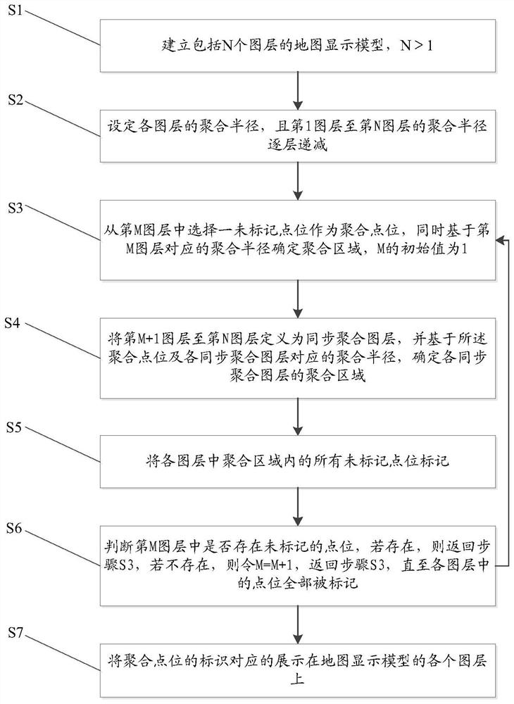
[0044] figure 2 It is a schematic flowchart of the electronic map point aggregation method in Embodiment 1 of the present invention. see figure 2 , this embodiment provides an electronic map point aggregation method, including:

[0045] Step S1, establishing a map display model including N layers, N>1;

[0046] Step S2, setting the aggregation radius of each layer, and the aggregation radius from the first layer to the Nth layer decreases layer by layer;

[0047] Step S3, select an unmarked point from the Mth layer as the aggregation point, and determine the aggregation area based on the aggregation radius corresponding to the Mth layer, and the initial value of M is 1;

[0048] Step S4, defining the M+1th layer to the Nth layer as a synchronous aggregation layer, and determining the aggregation area of ​​each synchronous aggregation layer based on the aggregation point and the aggregation radius corresponding to each synchronous aggregation layer;

[0049] Step S5, mark...

Embodiment 2

[0063] see figure 2 and Figure 4 , this embodiment provides an electronic map point aggregation device, including a modeling unit 1, a setting unit 2, a first processing unit 3, a second processing unit 4, a marking unit 5, a judging unit 6 and a display unit connected in sequence 7. The judging unit 6 is also connected to the first processing unit 3;

[0064] The modeling unit 1 is used to establish a map display model including N layers, where N>1;

[0065] The setting unit 2 is used to set the aggregation radius of each layer, and the aggregation radius of the first layer to the Nth layer decreases layer by layer;

[0066] The first processing unit 3 is used to select an unmarked point from the Mth layer as the aggregation point, and determine the aggregation area based on the aggregation radius corresponding to the Mth layer, and the initial value of M is 1;

[0067] The second processing unit 4 is used to define the M+1th layer to the Nth layer as a synchronous aggre...


PUM


Abstract

The invention discloses an electronic map point aggregation method and device, which can effectively solve the problems of display confusion and excessive consumption of performance resources caused by the display of massive points in a map. The method includes: establishing a map display model including N layers; setting the aggregation radius of each layer, and the aggregation radius from the first layer to the Nth layer decreases layer by layer; selecting an unidentified layer from the Mth layer The marked point is used as the aggregation point, and the aggregation area is determined based on the aggregation radius corresponding to the Mth layer. The initial value of M is 1; the M+1th layer to the Nth layer are defined as synchronous aggregation layers, and based on Aggregate points and the aggregation radius corresponding to each synchronous aggregation layer, determine the aggregation area of ​​each synchronous aggregation layer; mark all unmarked points in the aggregation area in each layer; judge whether there is an unmarked in the Mth layer If there are points, then return to step S3, if not, set M=M+1, return to step S3, until all the points in each layer are marked.

Description

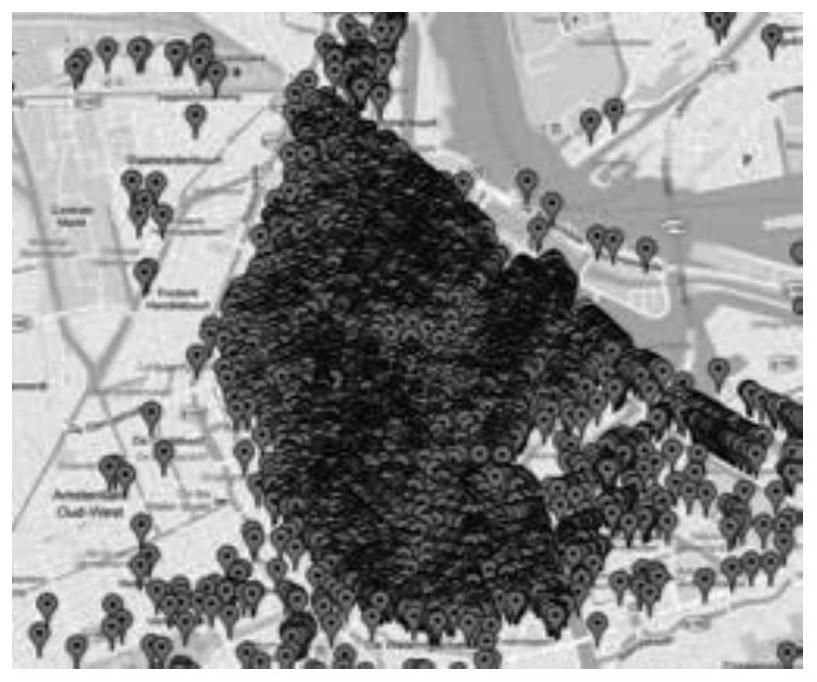
technical field [0001] The invention relates to the technical field of map information processing, in particular to a method and device for point aggregation of an electronic map. Background technique [0002] On an electronic map, a geometric point is usually used to represent a geographic location in a real space, and the geometric point is called a geographic point or a point element, referred to as a point. However, an area on the electronic map contains tens of thousands of points. If all the points are displayed directly, such as figure 1 As shown, the simultaneous display of these points will cover the base map of the map, which will make the user feel that the display of the electronic map is very chaotic, and even cause dense phobia. [0003] At present, most electronic map manufacturers provide map application programming interface APIs including point aggregation functions, which are basically implemented by JavaScript language. Since JavaScript is a front-end l...

Claims


Application Information

Patent Timeline
Patent Type & Authority Patents(China)
IPC IPC(8): G06F16/29
Inventor 耿继超李姿阅
Owner 汉华(易美)天津图像技术有限公司
Learn More