Lead-acid battery

A technology of lead-acid batteries and conductive sheets, which is applied in the direction of lead-acid batteries, lead-acid battery construction, secondary batteries, etc., can solve problems such as acid stratification, improve the utilization rate, reduce the probability of battery air leakage, and extremely The effect of cluster height reduction

Active Publication Date: 2019-01-18
TIANNENG BATTERY GROUP
View PDF9 Cites 6 Cited by
  • Summary
  • Abstract
  • Description
  • Claims
  • Application Information

AI Technical Summary

Problems solved by technology

In this technical solution, the lead-acid battery is placed horizontally. Since the height of the pole group is greater than the width and thickness under normal circumstances, the occurrence of acid stratification can be alleviated to a certain extent in the case of horizontal placement, but after a long time of use, There will still be acid stratification

Method used


Image

  • Lead-acid battery
  • Lead-acid battery
  • Lead-acid battery

Examples


Embodiment 1

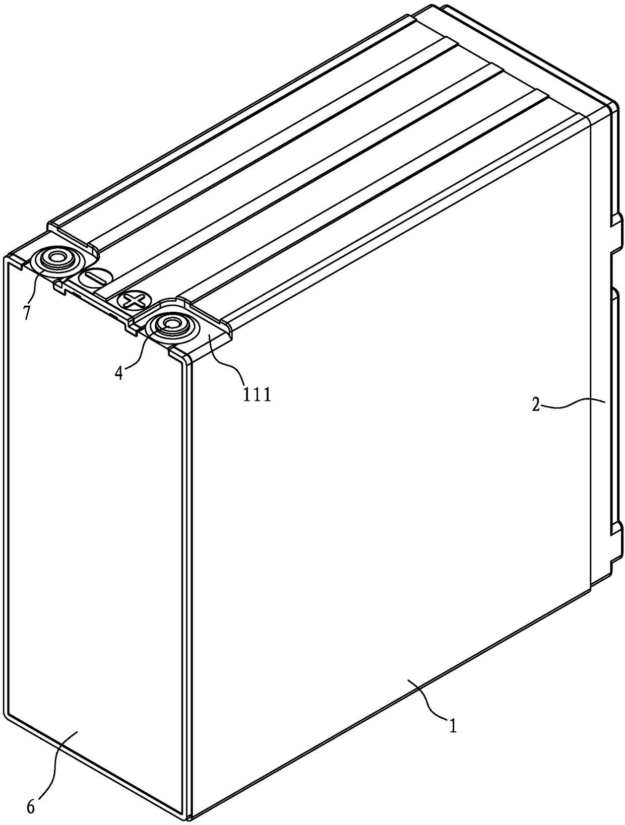
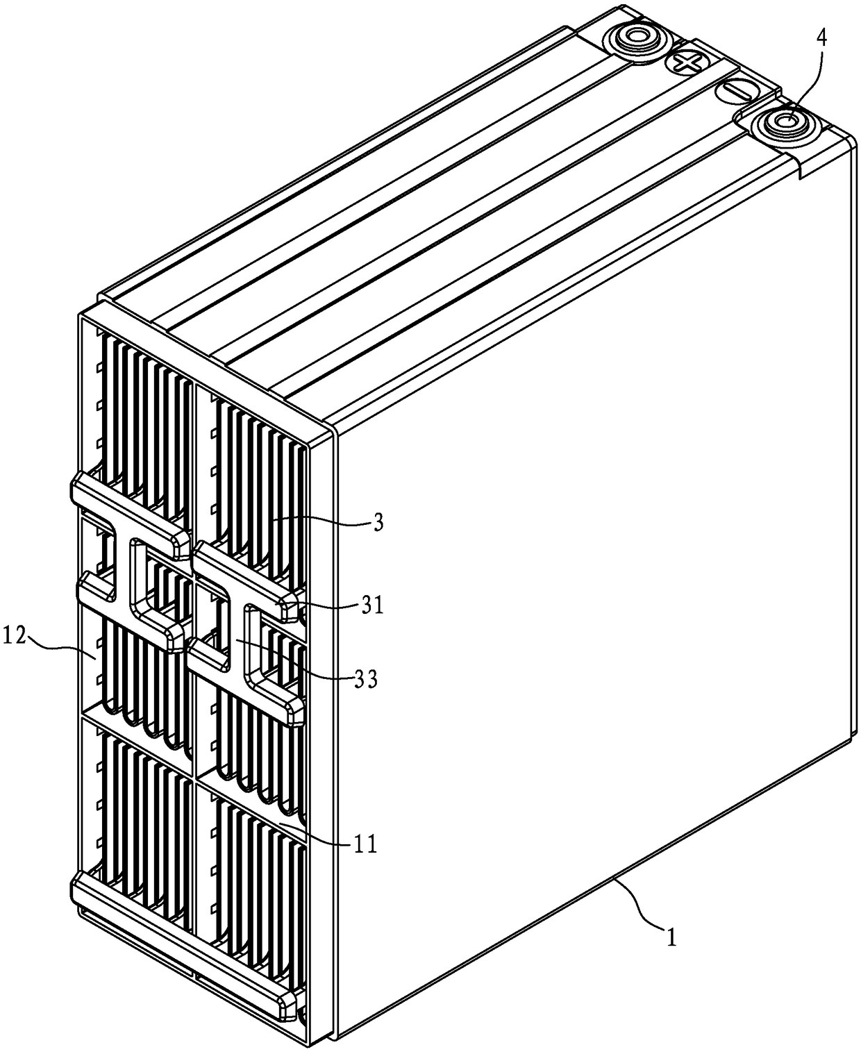
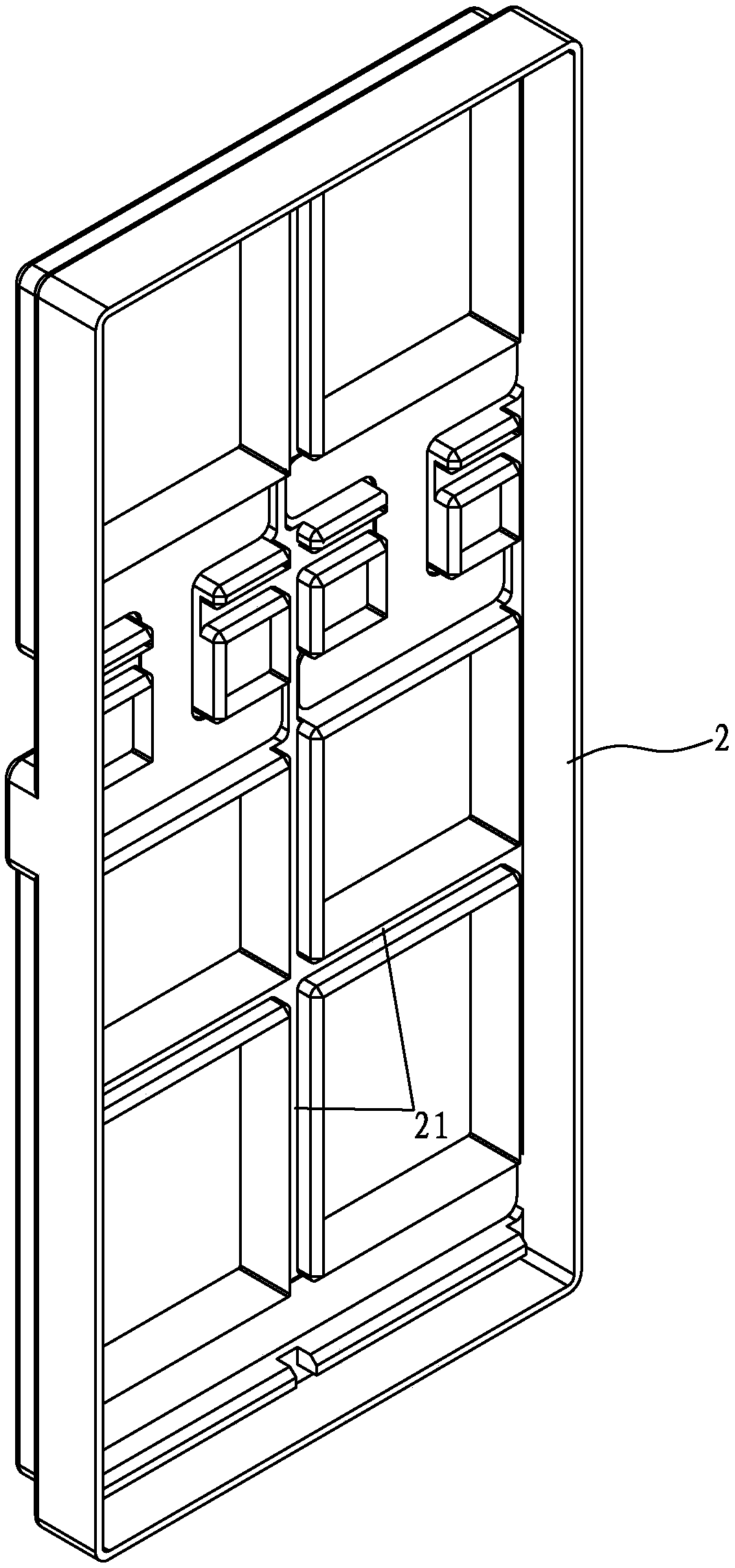
[0043] Such as Figure 1-13 As shown, a lead-acid storage battery includes: a tank body 1 with only one opening, and a partition plate 11 is arranged inside, and the partition plate 11 divides the cavity of the tank body 1 into several single cells 12, and the tank body 1 is relatively open. The bottom is provided with a liquid injection hole 13 corresponding to the single cell 12; a cover body 2 that cooperates with the tank body 1 to seal the opening; a number of pole groups 3 assembled in the tank body 1 and connected in series in sequence, each pole group 3 Bus bars (bus bar 31 and bus bar 32) with opposite polarities are arranged on both sides of the two sides, one side of the two sides is set facing the cover body 2, the other side is set back to the cover body 2, facing the cover body 2 The set bus bar 31 is connected through the bridge 33 extending into the cover body 2, and the bus bar 32 set back to the cover body 2 has poles 34 passing through the bottom of the tank...

Embodiment 2

[0052] Such as Figures 14 to 17 Shown is a schematic structural diagram of the second embodiment of the present invention, in which compared with the first embodiment of Example 1, the only difference is that the pole groups 3' are arranged in a 1×6 arrangement, and the assembly method of the terminal 4' different.

[0053] A lead-acid storage battery, comprising: a tank body 1' with only one opening, a cover body 2' cooperating with the tank body 1 to seal the opening; several pole groups 3' assembled in the tank body 1' and connected in series in sequence, each Bus bars (bus bar 31' and bus bar 32') with opposite polarities are arranged on both sides of each pole group 3', one side of the two sides is facing the cover body 2', and the other side is facing away from the cover body 2', the bus bar 31' set facing the cover 2' is directly connected by the extension of the bus bar, the bus bar 32' set back to the cover 2' has a pole 34' passing through the bottom of the groove,...


PUM


Abstract

The invention discloses a lead-acid battery, comprising: a tank body with only one opening; A lid body cooperating with that groove body to seal the opening; a plurality of pole groups assembled inside the tank body and serially connected in series; the terminal is arranged on the side of the tank body. when in use, the opening of the tank body is placed laterally, and the bus bar is in a horizontal state. as that positive bus bar and the negative bus bars are respectively arranged on the two sides of the pole group, the current density distribution is more uniform, the utilization rate of theactive material at each part of the pole plate is effectively improved, and the service life of the battery is prolonged. When in use, the opening of the tank body is placed laterally, and the bus bar is in a horizontal state, which is equivalent to the height of the electrode plate vertically placed with the short side as the pole group, so that the pole group height is lowered, the phenomenon of acid stratification is effectively alleviated, the concentration polarization is reduced, the active substances in each part of the electrode plate are utilized more uniformly, and the service lifeof the battery is prolonged.

Description

technical field [0001] The invention relates to the technical field of batteries, in particular to a lead-acid storage battery. Background technique [0002] The current valve-regulated sealed lead-acid battery adopts a lean liquid structure, and the electrolyte is adsorbed in the separator and plate. The tabs of the positive and negative plates are located on the same side of the upper part of the plate, and after assembly, the tabs are located on the upper part, divided into left and right sides. In the process of charging and discharging, the plate is high, which is prone to acid stratification and concentration polarization, which leads to differences in the utilization rate of active materials in each part, and there are large differences in each part of the plate. And because the tab is on the top of the pole plate, the current density on the top of the pole plate is high, the utilization rate of the active material is high, the upper part is easy to loose and fall of...

Claims


Application Information

Patent Timeline
Patent Type & Authority Applications(China)
IPC IPC(8): H01M10/12H01M2/20H01M2/04H01M50/147H01M50/503H01M50/507H01M50/528
CPCH01M10/121H01M50/166H01M50/502Y02E60/10Y02P70/50
Inventor 胡曙张和平韩峰方明学高根芳汪章杰酒涛涛姚秋实汤序锋代飞田庆山李丹施璐宋文龙
Owner TIANNENG BATTERY GROUP
Why Eureka
Try Eureka