Automatic soldering apparatus suitable for integrated circuitry

An integrated circuit, automatic technology, applied in the direction of assembling printed circuits with electrical components, tin feeding devices, auxiliary devices, etc., can solve problems such as errors and affecting quality

Inactive Publication Date: 2019-01-22
刘慧华
View PDF8 Cites 1 Cited by
  • Summary
  • Abstract
  • Description
  • Claims
  • Application Information

AI Technical Summary

Problems solved by technology

[0003] At present, the existing brazing device needs two sets of mechanisms to control the up and down movement and feeding of the welded pipe respectively when performing electric welding on the integrated circuit board. range, but will still affect the overall quality

Method used


Image

  • Automatic soldering apparatus suitable for integrated circuitry
  • Automatic soldering apparatus suitable for integrated circuitry
  • Automatic soldering apparatus suitable for integrated circuitry

Examples


Embodiment 1

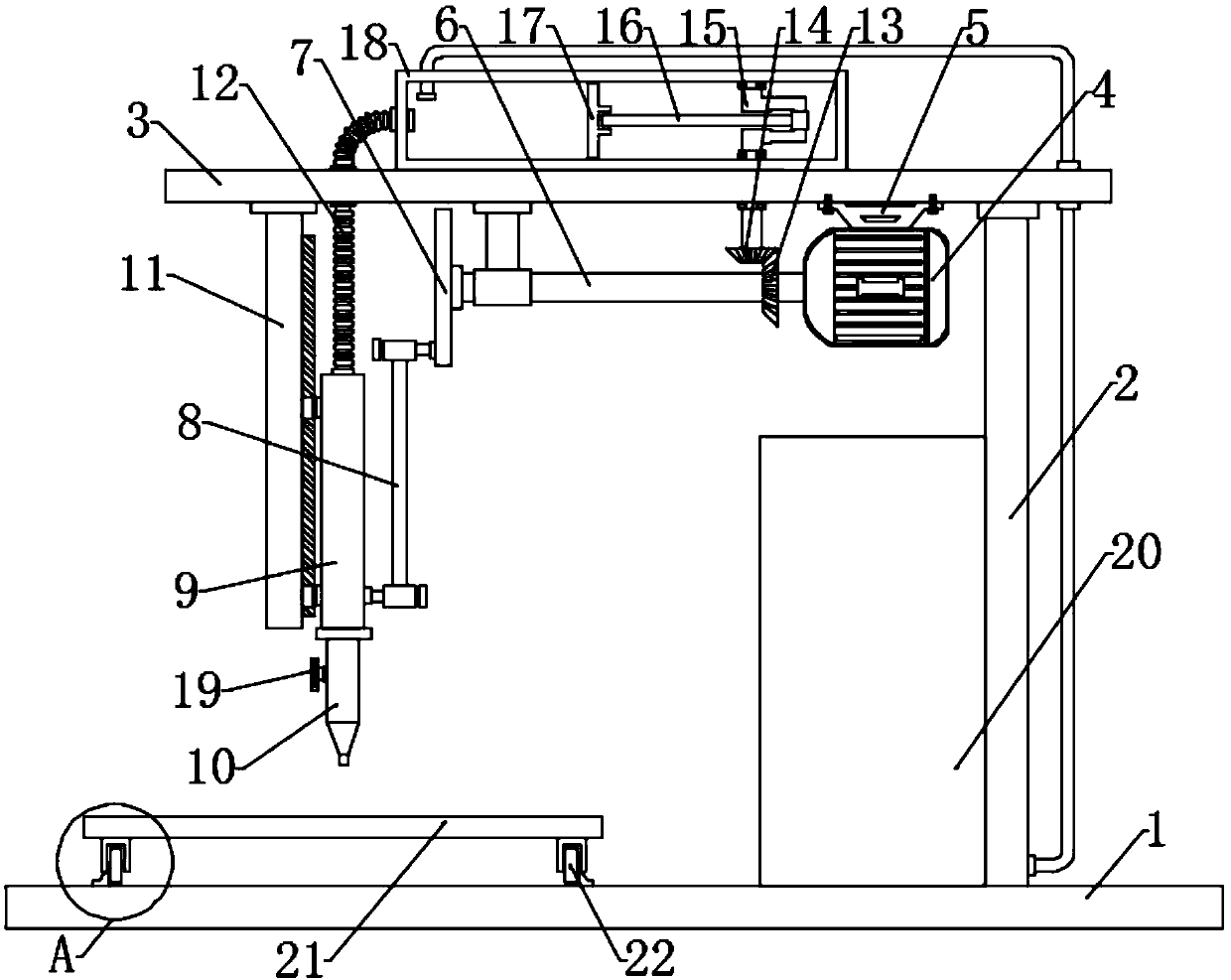
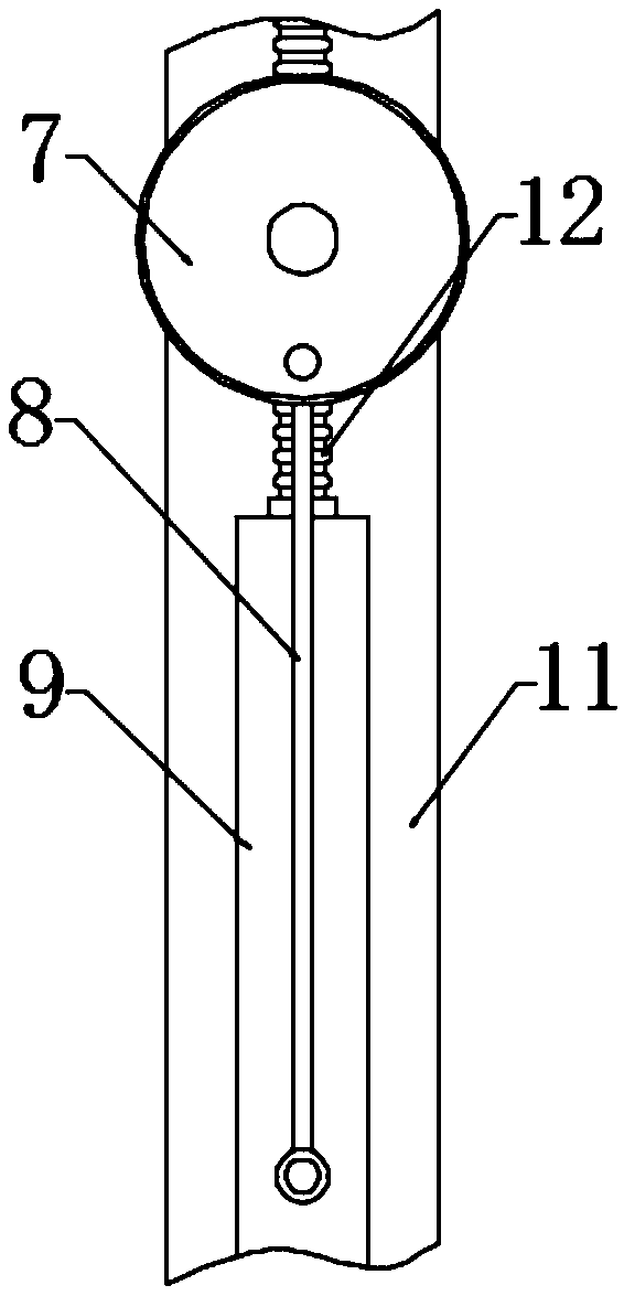
[0021] see Figure 1~3 , in an embodiment of the present invention, an automatic brazing device suitable for integrated circuits includes a bottom plate 1, a top plate 3, a turntable 7, a welding pipe 10, an injection pipe 18, and a material box 20; the bottom plate 1 is fixedly connected to a pillar 2, The upper end of the pillar 2 is fixedly connected to the top plate 3, and the drive motor 4 is installed under the top plate 3. Specifically, the drive motor 4 is fixedly connected to the motor base 5, and the motor base 5 is fixedly connected to the lower surface of the top plate 3 by bolts, and the output end of the drive motor 4 is connected to it in rotation. There is a driving shaft 6, the driving shaft 6 fits the lower end of the boom, the top of the boom is fixedly connected to the top plate 3, the driving motor 4 is connected to the power supply and the switch, and pressing the switch makes the driving motor 4 energized to drive the driving shaft 6 to rotate; the drivin...

Embodiment 2

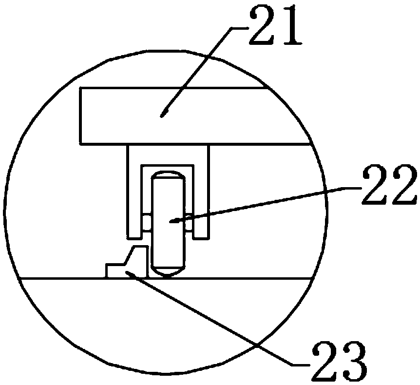
[0025] In order to make the technical solutions in this application more detailed and complete, now some supplements and explanations are made on the basis of the above-mentioned embodiment 1, so that the disclosure of the technical means adopted in this application is more sufficient, specifically, the supplements and explanations Part of the technical feature is that a workbench 21 is arranged under the welded pipe 10, and the four corners below the workbench 21 are rotatably connected with rollers 22. 23 restricts the moving direction of the rollers 22, so that the workbench 21 can only move in one direction, which helps the integrated circuit board to be transported smoothly in the assembly line and enters the next process.

[0026] The working principle of the present invention is: press the switch to make the drive motor 4 energized to drive the driving shaft 6 to rotate, and the rotating driving shaft 6 drives the turntable 7 to rotate, and then drives the storage gun 9 ...


PUM


Abstract

The invention discloses an automatic soldering apparatus suitable for integrated circuitry. The output end of a driving motor is rotationally connected with a driving shaft; the driving motor is connected with a power source and a switch via wires; the end of the driving shaft is fixedly connected with a turnplate; the outer edge of the turnplate is rotationally connected with the upper end of a connection bar; the lower end of the connection bar is rotationally connected with the lower portion of a storage gun; a first bevel gear is fixedly connected to the driving shaft; a second bevel gearis engaged with the top of the first bevel gear and is fixedly connected with the lower end of a crankshaft; an injection pipe is fixedly connected to the top of a top plate. the middle bend of the crankshaft is sleeved with the end of a push bar; the other end of the push bar is rotationally connected with the side of a piston; the edge of the piston is hermetically and slidably connected with the inner wall of the injection pipe. The automatic soldering apparatus provides spot welding by: driving the turnplate to rotate via the driving shaft and enabling the connection bar to drive the storage gun to reciprocate up and down under the action of slide feet and slide grooves.

Description

technical field [0001] The invention relates to industrial automation equipment, in particular to an automatic brazing device suitable for integrated circuits. Background technique [0002] Brazing refers to a welding method in which the solder below the melting point of the weldment and the weldment are heated to the melting temperature of the solder at the same time, and then the gaps in the solid workpiece are filled with liquid solder to connect the metals. When brazing, the oxide film and oil stain on the contact surface of the base metal should be removed first, so as to facilitate the function of the capillary after the solder is melted, and increase the wettability and capillary fluidity of the solder. According to the melting point of solder, brazing is divided into hard brazing and soft brazing. [0003] At present, the existing brazing device needs two sets of mechanisms to control the up and down movement and feeding of the welded pipe respectively when performi...

Claims


Application Information

Patent Timeline
Patent Type & Authority Applications(China)
IPC IPC(8): B23K3/00B23K3/06B23K3/08H05K3/34B23K101/42
CPCB23K3/00B23K3/06B23K3/0607B23K3/08H05K3/34
Inventor 刘慧华
Owner 刘慧华
Why Eureka
Try Eureka