Cross-platform motion control system for laser engraving machine

A technology of motion control system and laser engraving machine, which is applied in the direction of laser welding equipment, manufacturing tools, welding equipment, etc., can solve the problem of unintuitive parameter display, and achieve the effect of avoiding misoperation

Active Publication Date: 2019-01-22
广州里程科技发展有限公司
View PDF19 Cites 2 Cited by
  • Summary
  • Abstract
  • Description
  • Claims
  • Application Information

AI Technical Summary

Problems solved by technology

[0004] The technical problem solved by the present invention is to provide a laser engraving machine cross-platform motion control system to solve th

Method used


Image

  • Cross-platform motion control system for laser engraving machine
  • Cross-platform motion control system for laser engraving machine
  • Cross-platform motion control system for laser engraving machine

Examples


Embodiment 1

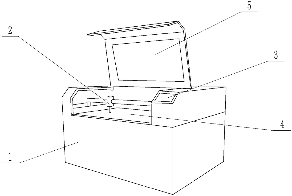
[0024] The embodiment is basically as attached figure 1 Shown: Laser engraving machine cross-platform motion control system, including server, control terminal and laser engraving machine, the server is connected with the control terminal and laser engraving machine respectively through wireless communication module signal, wireless communication module includes Bluetooth low energy communication module ( BLE) and BCM43143 model WIFI communication module.

[0025] The laser engraving machine includes a body 1, an outer cover 5, a carbon dioxide laser 2, an optoelectronic system, a cooling subsystem, a flat workbench 4, a smoke exhaust subsystem, an alarm device, and a control panel 3. The control panel 3 is provided with buttons and a display to control A motion control program is introduced into the panel 3, and the control panel 3 can control the laser engraving machine to work according to the motion control program.

[0026] The server is composed of a single-board comput...

Embodiment 2

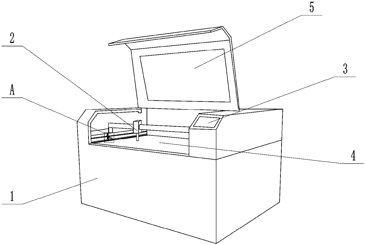
[0030] Such as figure 2 As shown, compared with Embodiment 1, the only difference is that a fume cleaning subsystem is also included. The applicant's laser engraving machine cross-platform motion control system mainly processes non-metallic intake pipes (hereinafter referred to as intake pipes), that is, it is used to cut connection holes on non-metallic intake pipes. In actual use, a relatively sealed working chamber is formed after the outer cover 5 is covered, and the cutting is performed in the working chamber, and a large amount of smoke and dust will be generated during the cutting process. For this part of the smoke and dust, the generally adopted method is to install exhaust equipment on the side of the working chamber to remove the smoke and dust escaping in the working chamber directly through negative pressure suction. However, since the intake pipe is processed, the actual working process is as follows: open the outer cover 5, fix the intake pipe on the flat work...


PUM


Abstract

The invention relates to the field of laser cutting, in particular to a cross-platform motion control system for a laser engraving machine. The system comprises the laser engraving machine, a server and a control terminal. The laser engraving machine comprises a laser, a photoelectric system, a cooling subsystem, a smoke discharge subsystem, a control panel and an information interaction module. The control terminal is in signal connection with the server and provided with a browser, the control terminal access the server through the browser, the server is in signal connection with the information interaction module, and the control terminal is provided with a display screen for feeding back information to users and allowing the users to input information. By adoption of the scheme, the problem of indirect parameter display caused by limitation of control panel area and key number of an existing laser engraving machine is solved.

Description

technical field [0001] The invention relates to the field of laser cutting, in particular to a cross-platform motion control system for a laser engraving machine. Background technique [0002] The existing laser engraving machine includes carbon dioxide laser, laser power supply, control panel, flat workbench, optical path system, cooling system and smoke exhaust system. The engraving system layout software is installed in the control panel, and the engraving system layout software needs to be started when using it. , design the image to be engraved, and determine the engraving position, so that the carbon dioxide laser performs laser engraving according to the designed engraving image and the determined engraving position. [0003] With the continuous expansion of the application range of laser engraving machines, there are also more and more application cases as supporting equipment for production lines. These devices can dynamically display processing parameters. However,...

Claims


Application Information

Patent Timeline
IPC IPC(8): B23K26/362B23K26/70
CPCB23K26/362B23K26/361B23K26/702
Inventor 徐志伟夏文华庾建军
Owner 广州里程科技发展有限公司
Why Eureka
Try Eureka