Tool fixture applied to bucket welding robot workstation

A welding robot, tooling and fixture technology, applied in the direction of manufacturing tools, welding equipment, auxiliary welding equipment, etc., can solve the problem of not being able to adapt to various sizes of buckets, and achieve the effect of simple structure, improved practicability, and avoidance of cumbersome operations.

Pending Publication Date: 2019-01-22
成都环龙智能机器人有限公司
View PDF8 Cites 2 Cited by
  • Summary
  • Abstract
  • Description
  • Claims
  • Application Information

AI Technical Summary

Problems solved by technology

[0004] The main purpose of the present invention is to provide a tooling fixture applied to a bucket welding robot workstation, to solve the problem in the prior art that it cannot adapt to buckets of various sizes

Method used


Image

  • Tool fixture applied to bucket welding robot workstation
  • Tool fixture applied to bucket welding robot workstation
  • Tool fixture applied to bucket welding robot workstation

Examples


Embodiment 1

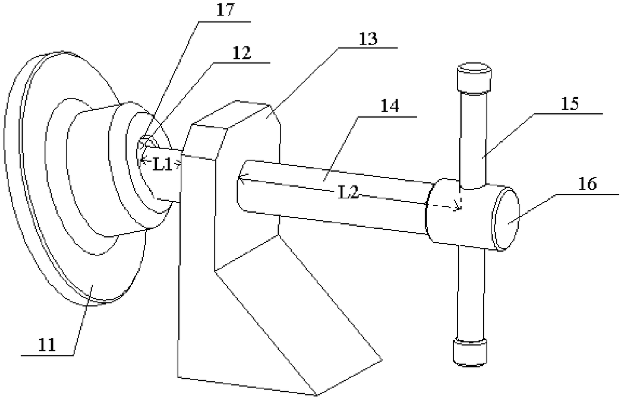
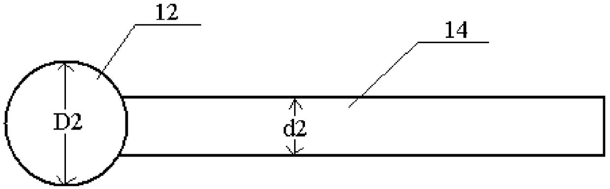
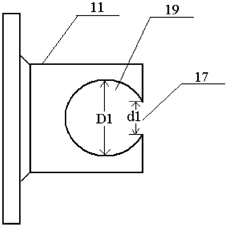
[0039] figure 1 It is a schematic diagram of the pressing mechanism applied to the bucket welding robot workstation according to the embodiment of the present invention; figure 2 yes figure 1 Schematic diagram of the self-locking screw rod; image 3 is a cross-sectional view of the floating pressure head in the figure.

[0040] Such as Figure 1-Figure 3 The shown pressing mechanism applied to the bucket welding robot workstation includes a floating pressure head 11, a self-locking screw rod 14, a support 13, and a trigger lever 15; the rear end of the floating pressure head 11 is provided with a self-locking wire The cavity 19 connected by the rod, the front end of the self-locking screw rod 14 is connected with a spherical part 12, the spherical part 12 is arranged in the cavity 19, the diameter D1 of the cavity 19 is greater than the diameter D2 of the spherical part 12, and the opening of the cavity 19 The diameter d1 is smaller than the diameter D2 of the spherical m...

Embodiment 2

[0044] Figure 4 It is a schematic diagram of another embodiment of the present invention applied to the pressing mechanism of the bucket welding robot workstation; Figure 5 yes Figure 4 Schematic diagram of the self-locking screw rod; Figure 6 yes Figure 4 Cross-sectional view of the floating indenter.

[0045] Such as Figure 4-Figure 6 The shown pressing mechanism applied to the bucket welding robot workstation includes a floating pressure head 21, a self-locking screw rod 24, a support 23, and a trigger lever 25; the rear end of the floating pressure head 21 is provided with a self-locking wire The cavity 29 that the rod 24 communicates, the front end of the self-locking screw rod 24 is connected with a spherical part 22, the spherical part 22 is arranged in the cavity 29, the diameter D1 of the cavity 29 is greater than the diameter D2 of the spherical part 22, and the diameter D2 of the cavity 29 The opening diameter d1 is smaller than the diameter D2 of the sph...

Embodiment 3

[0050] Figure 7 It is a schematic diagram of the tooling fixture applied to the bucket welding robot workstation in this embodiment. Such as Figure 7 As shown, the tooling fixture applied to the bucket welding robot workstation includes a positioning assembly and a support assembly supporting the positioning assembly; the positioning assembly includes two first positioning assemblies respectively arranged outside the two slopes of the bucket Assembly 1 and two second positioning assemblies 2 respectively arranged outside the two facades of the bucket; the first positioning assembly 1 and the second positioning assembly 2 are provided with a universal pressing mechanism 3; The support assembly includes a "mouth"-shaped support frame 4 and a support plate arranged on the support frame 4 and matched with the bucket opening surface; the first positioning assembly 1 is connected to the support plate; the The second positioning assembly 2 is connected with the support frame 4 . ...


PUM


Abstract

The invention provides a tool fixture applied to a bucket welding robot workstation. The tool fixture comprises a positioning component, a support component and a width adjusting mechanism. The positioning component comprises two first positioning subassemblies and two second positioning subassemblies, and universal pressing mechanisms are arranged on the first positioning subassemblies and the second positioning subassemblies respectively. Each of the universal pressing mechanisms comprises a float pressing head, a self-locking screw rod, a support seat and a wrench rod, wherein the support seat is used for fixing the self-locking screw rod, the wrench rod is connected to a tail end of the self-locking screw rod, a cavity communicated with the self-locking screw rod is formed in a rear end of the float pressing head, a spherical piece is connected with a front end of the self-locking screw rod and arranged inside the cavity, a diameter of the cavity is larger than that of the spherical piece, and a diameter of an opening of the cavity is smaller than that of the spherical piece. The support component supports the positioning component and comprises a support frame and support plates which matched with an opening face of a bucket. The width adjusting mechanism is used for adjusting width between the two first positioning subassemblies.

Description

technical field [0001] The invention relates to the technical field of components applied to a bucket welding robot workstation, in particular, to a tooling fixture applied to a bucket welding robot workstation. Background technique [0002] In the prior art, for buckets of different models and sizes, special fixtures are used. Because the bucket is large in size and heavy in weight, it is necessary to turn over the bucket during robot welding, and robot welding has high requirements for the accuracy of the welding seam position. If the bucket or its parts are turned over Changes in position during the process will seriously affect the quality of welding. Therefore, the current robot workstations for bucket welding all use special fixtures, the purpose of which is to fix the bucket well and minimize thermal deformation during the welding process. However, the existing fixtures are difficult to meet the welding of buckets of various sizes at the same time, and their practic...

Claims


Application Information

Patent Timeline
Patent Type & Authority Applications(China)
IPC IPC(8): B23K37/04
CPCB23K37/0443
Inventor 敬建雄
Owner 成都环龙智能机器人有限公司
Why Eureka
Try Eureka