Electrically programmable metal fuse

a metal fuses and electrical programming technology, applied in the field of metal electrical fuses, can solve the problems of excessive collateral structural damage to surrounding structures, difficult control of electromigration in metal lines, etc., and achieve the effects of preventing thermal cracking, reducing required power, and preventing metal from diffusing

Active Publication Date: 2013-04-16
GLOBALFOUNDRIES US INC
View PDF10 Cites 22 Cited by
  • Summary
  • Abstract
  • Description
  • Claims
  • Application Information

AI Technical Summary

Benefits of technology

[0005]A metal electrically programmable fuse (“eFuse”) includes a metal strip, having a strip width, of a metal line adjoined to wide metal line portions, having widths greater than the strip width, at both ends of the metal strip. The strip width can be a lithographic minimum dimension, and the ratio of the length of the metal strip to the strip width is greater than 5 to localize heating around the center of the metal strip during programming. Localization of heating reduces required power for programming the metal eFuse. Further, a gradual temperature gradient is formed within a length that is longer than the Blech length during the programming within the metal strip so that electromigration of metal gradually occurs reliably at the center portion of the metal strip. Metal line portions are provided at the same level as the metal eFuse to physically block debris generated during programming, and to prevent metallic materials from the programmed fuse from diffusing outside of the space defined by these “blocking lines” during product operation. Further, additional metal lines and / or metal vias can be placed at different wiring levels 1) to prevent debris from escaping the area of the metal eFuse; 2) to prevent thermal cracking from propagating outside the area of the eFuse during programming; and 3) to prevent metal from diffusing out of the eFuse region during the product operation.

Problems solved by technology

However, controlling electromigration in a metal line has been very difficult, and programming of prior art metal fuses has produced a combination of voiding and fusing between metal line and a metallic liner, or an uncontrolled blow.
If the programming power is too high, collateral structural damage to surrounding structures can be too extensive; impact to reliability of neighboring metal lines and introducing reliability concerns.

Method used


Image

  • Electrically programmable metal fuse
  • Electrically programmable metal fuse
  • Electrically programmable metal fuse

Examples


first embodiment

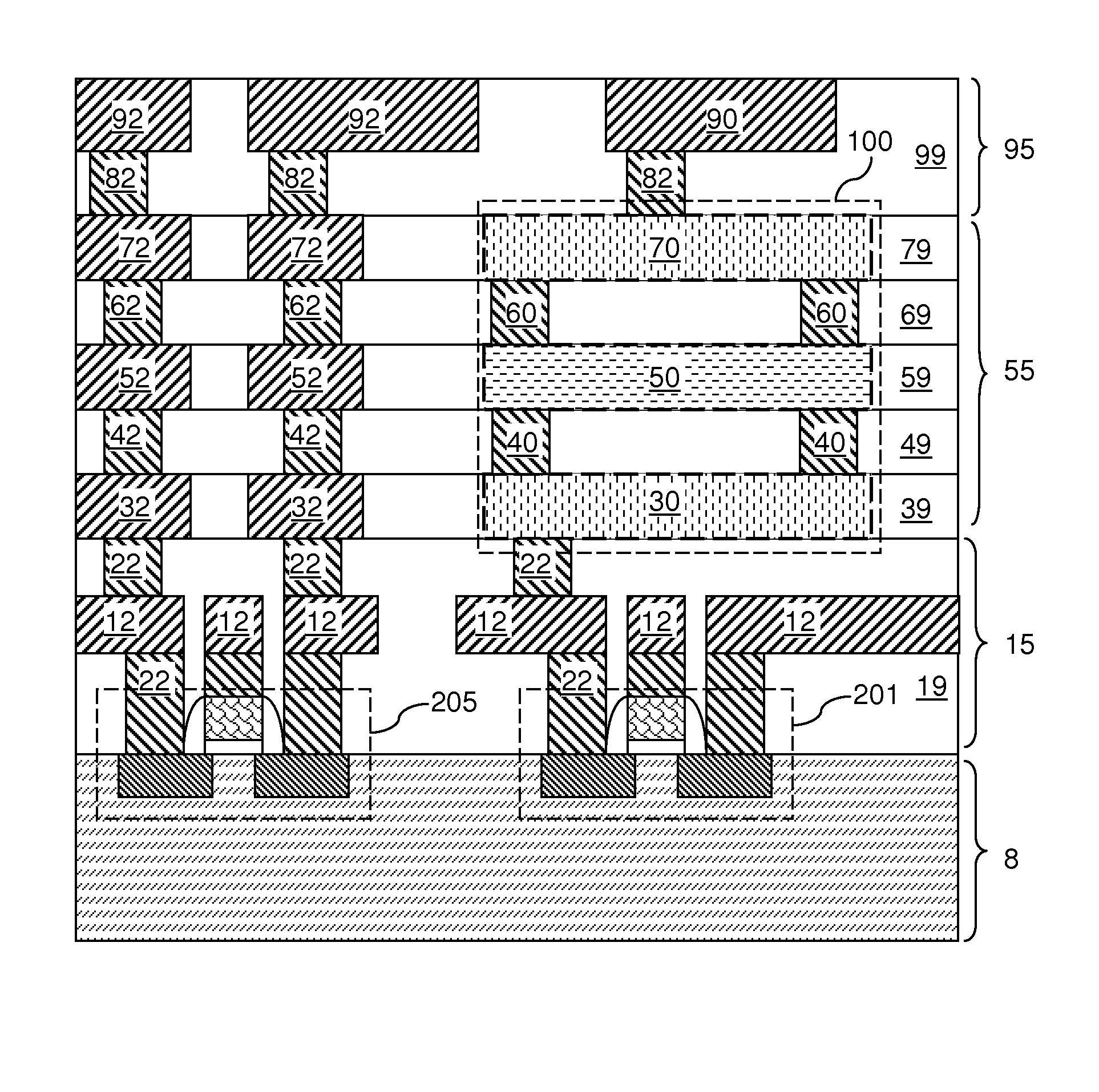
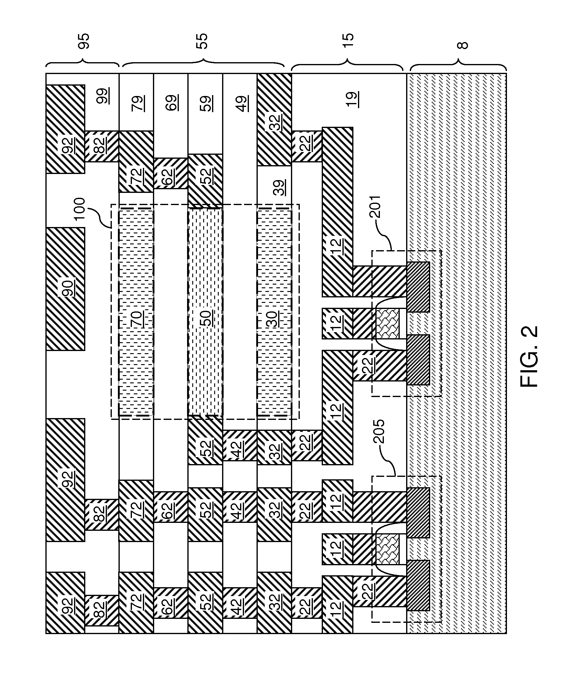
[0018]Referring to FIG. 2 and FIGS. 3A-3C, a first exemplary eFuse structure according to the present disclosure includes a stack, from bottom to top, of a semiconductor substrate 8, underlying interconnect structure layers 15, electrically programmable fuse-including (“e-Fuse-including”) interconnect structure layers 55, and overlying interconnect structure layers 95. The semiconductor substrate 8 includes a semiconductor material layer, and may be a bulk semiconductor substrate or a semiconductor-on-insulator (SOI) substrate. A programming transistor 201 for programming an electrically programmable fuse 100 can be provided on the semiconductor substrate 8. Further, additional semiconductor devices 205 such as field effect transistors, junction transistors, diodes, capacitors, inductors, resistors, and / or optical communication devices as known in the art can also be formed on the semiconductor substrate 8.

[0019]The underlying interconnect level layer 15 includes at least one underl...

second embodiment

[0058]Referring to FIGS. 7A-7E, a variation of the second exemplary eFuse structure according to the present disclosure can substitute each or any of the first upper via level metal structure 60A, the second upper via level metal structure 60B, the first lower via level metal structure 40A, and the second lower via level metal structure 40B with a via level metal structure of unitary construction (i.e., in a single piece) having a constant width along a lengthwise direction, and extending along a lengthwise direction of the first metal line portion 54 or a lengthwise direction of the second metal line portion 56. Thus, one or more of the first upper via level metal structure 60A, the second upper via level metal structure 60B, the first lower via level metal structure 40A, and the second lower via level metal structure 40B is a via level structure having a shape of a metal line.

[0059]The via level metal structures (60A, 60B, 40A, 40B) of unitary construction help confine the heat ge...


PUM

PropertyMeasurementUnit
resistanceaaaaaaaaaa
aspect ratioaaaaaaaaaa

Abstract

A metal electrically programmable fuse (“eFuse”) includes a metal strip, having a strip width, of a metal line adjoined to wide metal line portions, having widths greater than the metal strip width, at both ends of the metal strip. The strip width can be a lithographic minimum dimension, and the ratio of the length of the metal strip to the strip width is greater than 5 to localize heating around the center of the metal strip during programming. Localization of heating reduces required power for programming the metal eFuse. Further, a gradual temperature gradient is formed during the programming within a portion of the metal strip that is longer than the Blech length so that electromigration of metal gradually occurs reliably at the center portion of the metal strip. Metal line portions are provides at the same level as the metal eFuse to physically block debris generated during programming.

Description

BACKGROUND[0001]The present disclosure relates to semiconductor structures and particularly to metal electrical fuses that can be formed in a back-end-of-line (BEOL) interconnect structures and methods of programming the same.[0002]Electrical fuses and electrical antifuses are used in the semiconductor industry to implement array redundancy, field programmable arrays, analog component trimming circuits, and chip identification circuits. Once programmed, the programmed state of an electrical fuse or an electrical antifuse does not revert to the original state on its own, that is, the programmed state of the fuse is not reversible. For this reason, electrical fuses and electrical antifuses are called One-Time-Programmable (OTP) memory elements.[0003]FIG. 1 illustrates a circuit schematic of a circuitry including an electrically programmable fuse (“eFuse”) 1100. The electrically programmable fuse 1100 and a programming circuit 1200 are connected in a series connection between a power s...

Claims


Application Information

Patent Timeline
Patent Type & Authority Patents(United States)
IPC IPC(8): H01L29/00H01L23/525H01H37/76
CPCG11C17/16H01L23/5256H01L27/0207G11C29/785H01L2924/0002
Inventor LI, BAOZHENTIAN, CHUNYAN E.YANG, CHIH-CHAO
Owner GLOBALFOUNDRIES US INC
Why Eureka
Try Eureka