
Sleeve valve pipe capable of resisting pulling force and floating force on hole protecting sleeve pipe

A sleeve valve tube and sleeve technology, applied in the sleeve valve tube field, can solve the problems of large resistance and inability to effectively fix the PVC sleeve valve flower tube, etc., and achieve the effects of effective and reasonable composition, good promotion and application prospects, and convenient operation

Active Publication Date: 2019-01-22
CCFEB CIVIL ENG
View PDF3 Cites 2 Cited by
  • Summary
  • Abstract
  • Description
  • Claims
  • Application Information

AI Technical Summary

Problems solved by technology

Since the resistance of the hole wall and casing material is relatively large when the protective hole casing is pulled out, and under the buoyancy in the hole, the PVC sleeve valve flower tube will move upward at the same time, so the PVC sleeve valve flower tube cannot be effectively fixed

Method used


Image

  • Sleeve valve pipe capable of resisting pulling force and floating force on hole protecting sleeve pipe
  • Sleeve valve pipe capable of resisting pulling force and floating force on hole protecting sleeve pipe
  • Sleeve valve pipe capable of resisting pulling force and floating force on hole protecting sleeve pipe

Examples


Embodiment

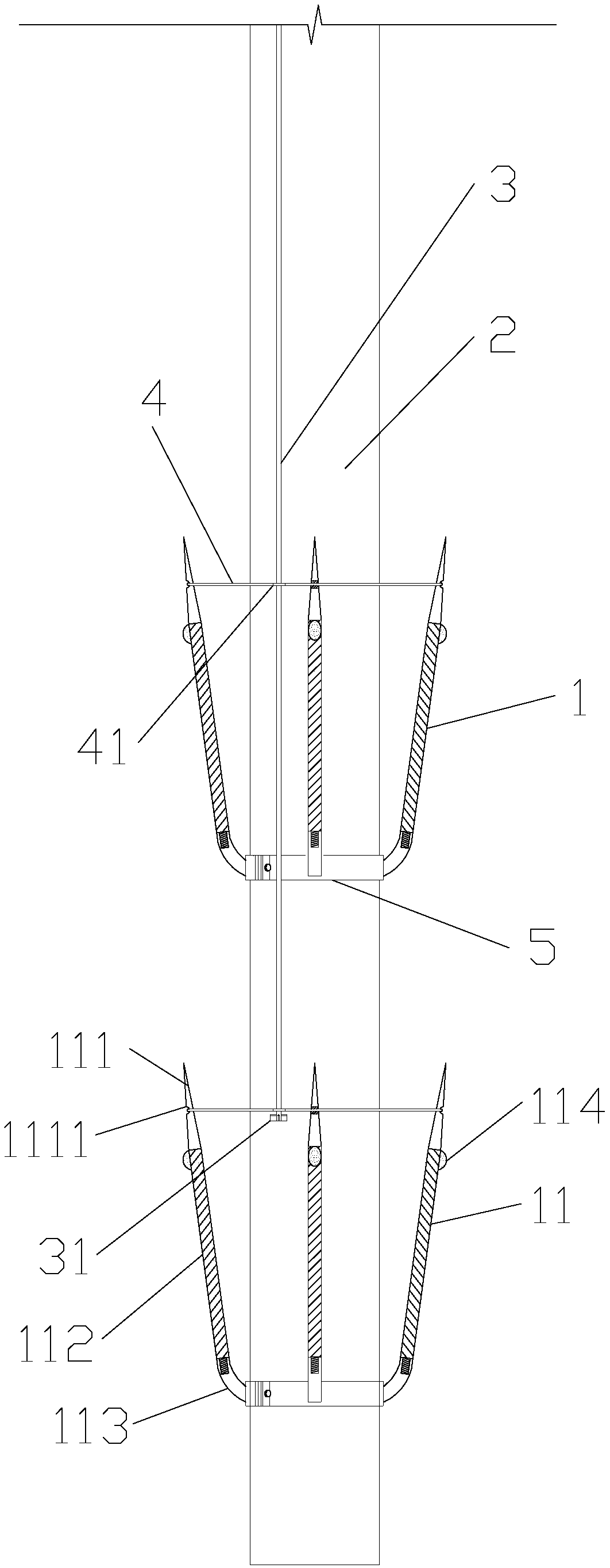
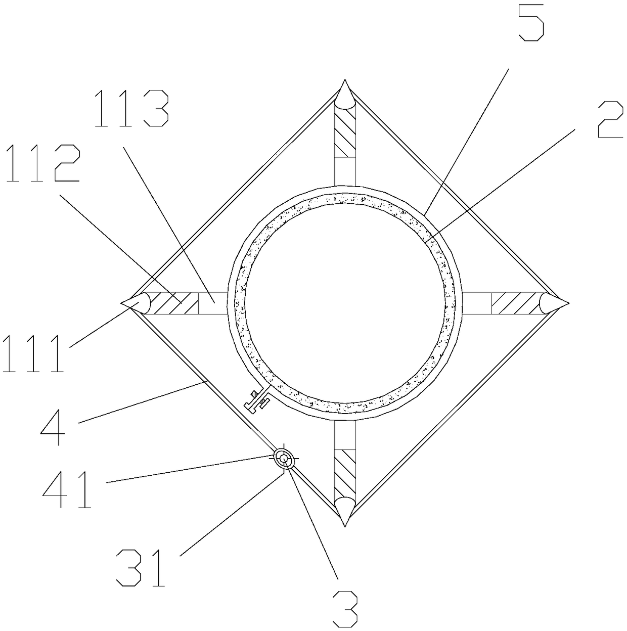
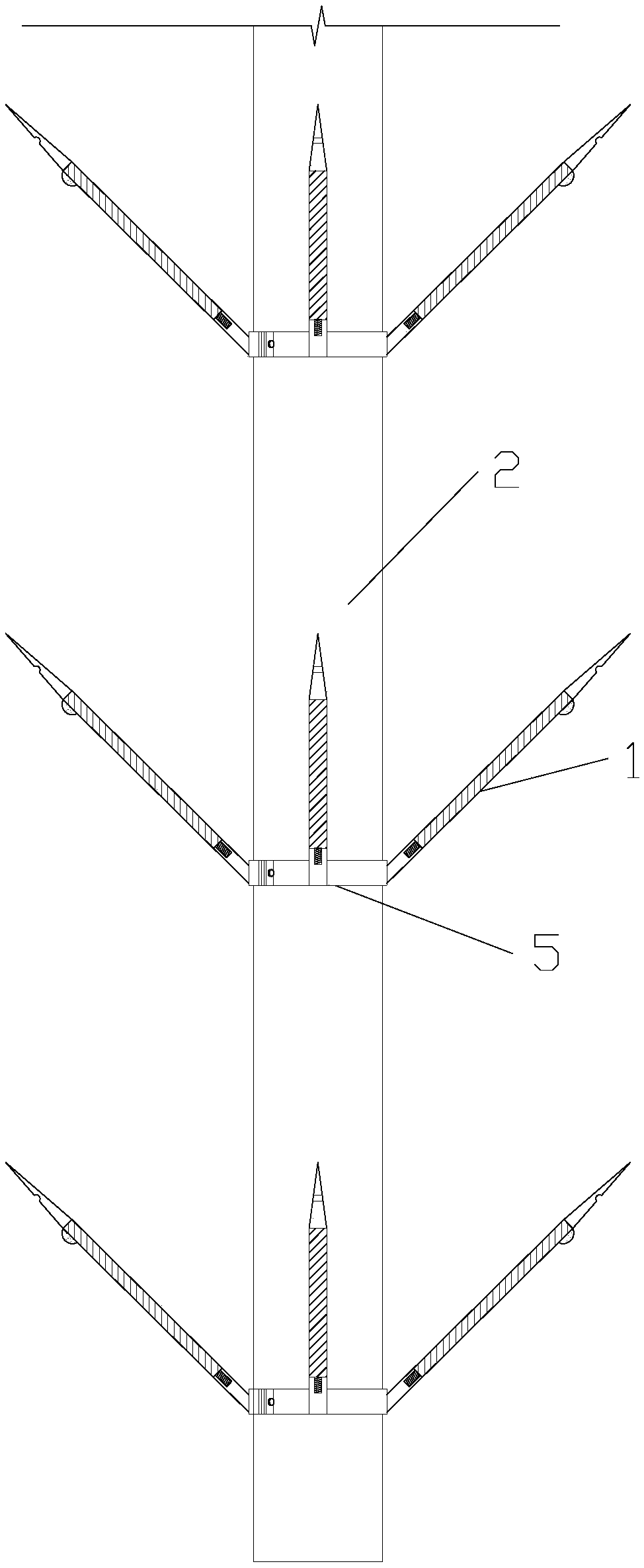
[0036] A sleeve valve tube that resists the pull-out and buoyancy forces of a grommet casing, see figure 1 , figure 2 , image 3 ,include:

[0037] PVC sleeve flower tube 2;

[0038] At least one set of pointed clips 1, said pointed clips 1 comprising a plurality of pointed clips 11 ( figure 1 , figure 2 , image 3 , Figure 4 , Figure 5 Shown in the case of installing four pointed clips 11); the pointed clip 11 includes a pointed head 111, a strip middle 112 and an elastic strip tail 113 connected in sequence; the pointed The clip 11 is installed on the PVC sleeve valve flower tube 2 through the strip tail 113; the pointed head 111 has a groove 1111 facing away from the PVC sleeve valve flower tube 2;

[0039] There is an elastic clip binding ring 4, which is provided with a drawstring threading ring 41 (see Image 6 , Figure 7 ); when the clip binding ring 4 is embedded in the groove 1111 of the pointed head 111, the clip binding ring 4 will tighten the pointed...


PUM


Abstract

The invention discloses a sleeve valve pipe capable of resisting pulling force and floating force on a hole protecting sleeve pipe. The pipe comprises a PVC sleeve valve floral pipe, at least one pointed clamping strip set, elastic clamping strip binding rings and binding ring pulling ropes; pointed clamping strips comprise pointed head portions, middle strip-shaped portions and elastic strip-shaped tail portions; the pointed clamping strips are installed on the PVC sleeve valve floral pipe through the strip-shaped tail portions, and grooves away from the PVC sleeve valve floral pipe are formed in the pointed head portions; pulling rope penetrating rings are arranged on the clamping strip binding rings; the clamping strip binding rings are embedded in the grooves in the pointed head portions, and the pointed clamping strips are bound to the PVC sleeve valve floral pipe by utilizing the clamping strip binding rings, so that the included angle between the pointed clamping strips and thePVC sleeve valve floral pipe is 0-5 degrees; when the clamping strip binding rings fracture or are separated from the grooves in the pointed head portions, the included angle between the pointed clamping strips and the PVC sleeve valve floral pipe is 30-50 degrees. It can be prevented that the PVC sleeve valve floral pipe moves upward under the upward pulling and floating effects of the hole protecting sleeve pipe, the construction efficiency is improved, and the pouring quality is ensured.

Description

technical field [0001] The invention relates to a sleeve valve pipe in an underground grouting reinforcement project, in particular to a sleeve valve pipe resisting the pulling force and buoyancy of a hole-protecting casing. Background technique [0002] With the continuous increase of my country's urbanization process, the development of above-ground space is becoming increasingly tense, which in turn leads to a gradual increase in the demand for underground space development. Base reinforcement and prevention of bottom subsidence are the premise of underground space development. Grouting has always been an effective method for base reinforcement and bottom subsidence prevention. Using sleeve valve pipe grouting can better control the grouting range and grouting pressure, and can achieve Timed, fixed point, quantitative and repeated grouting. Since the grouting area of ​​the sleeve valve tube is mostly unstable soil, it is necessary to use a protective sleeve to prevent th...

Claims


Application Information

Patent Timeline
Patent Type & Authority Applications(China)
IPC IPC(8): E02D15/04
CPCE02D15/04
Inventor 陈亚军吕涛刘德才王文王浪
Owner CCFEB CIVIL ENG
Learn More