Brake pad and brake friction pair using same

A technology of brake pads and friction blocks, which is applied in the field of automobile/high-speed rail accessories, can solve the problems of difficult to meet the rear wheel braking requirements of heavy-duty commercial vehicles, low absolute braking torque, unstable friction performance, etc., to prevent the block from falling off. , the braking performance is stable, the effect of improving the impact resistance performance

Active Publication Date: 2020-07-14
BEIJING TIANYISHANGJIA NEW MATERIAL
View PDF8 Cites 0 Cited by
  • Summary
  • Abstract
  • Description
  • Claims
  • Application Information

AI Technical Summary

Problems solved by technology

However, the absolute braking torque of disc brakes will be lower than that of drum brakes, and it is difficult to meet the rear wheel braking requirements of heavy-duty commercial vehicles.
On the other hand, although the absolute braking force of drum brakes is large, the phenomenon of insufficient braking force in long downhill braking due to the heat attenuation of the brakes during use will also occur.
At the same time, in order to solve this problem, water is often sprayed on the brake drum to cool down, which will cause the brake drum to burst and endanger driving safety.
[0003] At present, the brake friction pairs are all made of resin-based composite materials and cast iron brake discs / drums. Chinese patent CN104327800B discloses a resin-based friction material for brake pads, which is composed of phenolic resin, tin sulfide, calcium carbonate, aluminum oxide, white Composed of carbon black, polyacrylonitrile fiber and aramid fiber, it has the advantages of good stability, high hardness, and excellent friction resistance. However, problems such as high-temperature structural instability and frictional performance instability may occur during thermal decay tests. , and the sulfide is used in the material of the brake pad, which is easy to cause environmental pollution
In addition, traditional brake pads adopt an overall slotted structure, such as figure 1 shown, it is not conducive to heat dissipation

Method used


Image

  • Brake pad and brake friction pair using same
  • Brake pad and brake friction pair using same
  • Brake pad and brake friction pair using same

Examples


Embodiment 1

[0044] The raw material composition of the friction block: see Table 1.

[0045] Preparation:

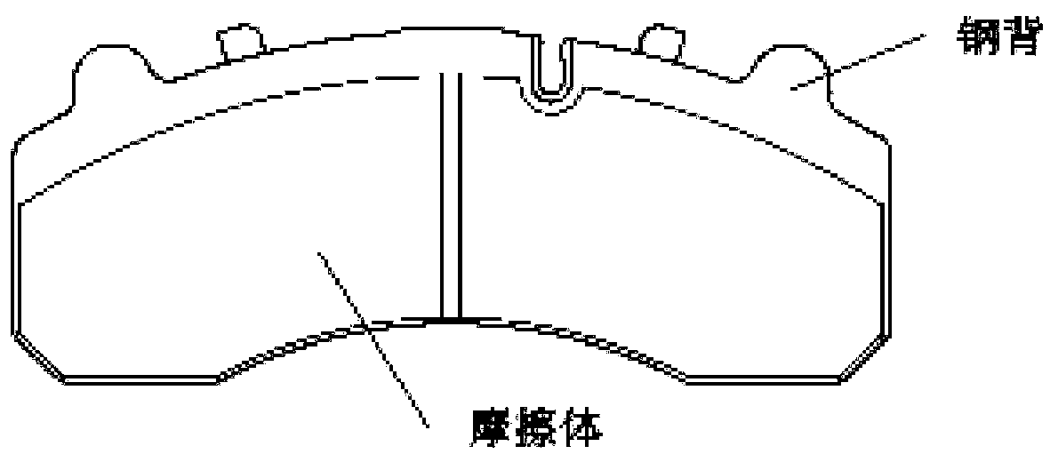
[0046] (1) Clean, sandblast, and pre-coat the steel back connected to the friction block of the brake pad, and wait for use after the treatment is completed;

[0047] (2) Put the raw materials used into the mixer and mix them for 20 minutes;

[0048] (3) Weigh the mixed powder according to the design weight, add it into the cavity, and press it, the pressing pressure is 350MPa, and the holding time is 20s;

[0049] (4) Carry out three-stage sintering of the pressed compact and the pretreated steel back under a hydrogen protective atmosphere, the first stage of normal pressure sintering, the sintering temperature is 1000 ° C, and the holding time is 80 minutes; the second stage is pressurized For sintering, the sintering temperature is constant, the pressure is 2.5 MPa, and the pressure is kept for 30 minutes; the third stage of normal pressure sintering, the sintering temperature ...

Embodiment 2

[0054] The raw material composition of the friction block: see Table 1.

[0055] Preparation:

[0056] (1) Clean, sandblast, and pre-coat the steel back connected to the friction block of the brake pad, and wait for use after the treatment is completed;

[0057] (2) Put the raw materials used into the mixer and mix for 30 minutes;

[0058] (3) Weigh the mixed powder according to the design weight, add it into the cavity, and press it, the pressing pressure is 450MPa, and the holding time is 10s;

[0059] (4) Carry out three-stage sintering of the pressed compact and the pretreated steel back under a hydrogen protective atmosphere, the first stage of normal pressure sintering, the sintering temperature is 980 ° C, and the holding time is 100 minutes; the second stage is pressurized For sintering, the sintering temperature is constant, the pressure is 4.5 MPa, and the pressure is kept for 20 minutes; the third stage of normal pressure sintering, the sintering temperature is 1100...

Embodiment 3

[0064] The raw material composition of the friction block: see Table 1.

[0065] Preparation:

[0066] (1) Clean, sandblast, and pre-coat the steel back connected to the friction block of the brake pad, and wait for use after the treatment is completed;

[0067] (2) Put the raw materials used into the mixer and mix for 40 minutes;

[0068] (3) Weigh the mixed powder according to the design weight, add it into the cavity, and press it, the pressing pressure is 500MPa, and the holding time is 10s;

[0069] (4) Carry out three-stage sintering of the pressed compact and the pretreated steel back under a hydrogen protective atmosphere, the first stage of normal pressure sintering, the sintering temperature is 1050 ° C, and the holding time is 120 minutes; the second stage is pressurized For sintering, the sintering temperature is constant, the pressure is 0.5MPa, and the pressure is maintained for 20 minutes; the third stage of normal pressure sintering, the sintering temperature...


PUM


Abstract

The invention belongs to the technical field of automobile brake systems, in particular to a brake friction pair and a preparation method thereof. The friction pair comprises a brake disc and a brakepad, wherein the brake pad is prepared through mixing, pressing and sintering; the brake pad comprises a friction material and a steel back; and the friction material comprises the following raw materials in parts by weight: iron powder 15-35 parts of iron powder, 2-6 parts of aluminum powder, 0.5-2 parts of phosphorus iron powder, 2-8 parts of flake graphite, 5-10 parts of low carbon ferrochromium, 2-5 parts of zirconium oxide, 2-5 parts of aluminum oxide and 40-60 parts of copper powder. According to the brake friction pair, the problems of insufficient absolute power of the disc brake in the prior art and thermal recession of braking force in continuous braking on up and down ramps are solved. The invention provides the brake friction pair with short braking distance, no obvious thermalrecession, stable friction coefficient and light weight and the preparation method of the brake friction pair.

Description

technical field [0001] The invention belongs to the technical field of automobile / high-speed rail accessories, and in particular relates to a brake pad and a brake friction pair using the same. Background technique [0002] The basic braking device of automobile / high-speed rail adopts a friction pair structure composed of brake disc and brake pad. During the braking process, the friction pair is often under high temperature, high thermal stress and other working conditions, which seriously restricts the service life of the brake. Braking devices mainly include disc brakes and drum brakes. Compared with drum brakes, disc brakes have the characteristics of stable braking torque, good heat dissipation, and light weight. The country currently imposes mandatory requirements on trailers and dangerous goods vehicles, that is, the front brakes must use disc brakes. However, the absolute braking torque of disc brakes will be lower than that of drum brakes, and it is difficult to mee...

Claims


Application Information

Patent Timeline
Patent Type & Authority Patents(China)
IPC IPC(8): F16D69/02C09K3/14
CPCF16D69/027F16D2200/0004F16D2250/0061
Inventor 吴佩芳释加才让党一纵崔新亮范叶明
Owner BEIJING TIANYISHANGJIA NEW MATERIAL
Why Eureka
Try Eureka