Station laying method for ground surface settlement monitoring of mining area ground surface settlement by three-dimensional laser scanning

A surface subsidence, three-dimensional laser technology, which is used in measurement devices, surveying and navigation, height/level measurement, etc., can solve the problems of difficulty in matching point clouds during data processing, the distance between observation stations is not fixed, and the position of observation stations is not fixed. Achieve uniform distribution of point cloud data, reasonable scanning range, and avoid blind spots.

Active Publication Date: 2019-01-22
ANHUI UNIVERSITY
View PDF36 Cites 8 Cited by
  • Summary
  • Abstract
  • Description
  • Claims
  • Application Information

AI Technical Summary

Problems solved by technology

However, there is still no method for laying out monitoring points for surface subsidence in mining areas for 3D laser scanning, which leads to some problems in the follow-up monitoring and data processing.
In the existing method of using a three-dimensional laser scanner for mining settlement monitoring, the station of the three-dimensional laser scanner is not fixed, the observation sequence of the observation station is not fixed, the position of the observation station for each period of observation is not fixed, and the distance between the observation stations is not fixed. Problems such as difficulty in matching point clouds during post-data processing

Method used


Image

  • Station laying method for ground surface settlement monitoring of mining area ground surface settlement by three-dimensional laser scanning
  • Station laying method for ground surface settlement monitoring of mining area ground surface settlement by three-dimensional laser scanning
  • Station laying method for ground surface settlement monitoring of mining area ground surface settlement by three-dimensional laser scanning

Examples


Embodiment Construction

[0028] The following will clearly and completely describe the technical solutions in the embodiments of the present invention with reference to the accompanying drawings in the embodiments of the present invention. Obviously, the described embodiments are only some, not all, embodiments of the present invention. Based on the embodiments of the present invention, all other embodiments obtained by persons of ordinary skill in the art without creative efforts fall within the protection scope of the present invention.

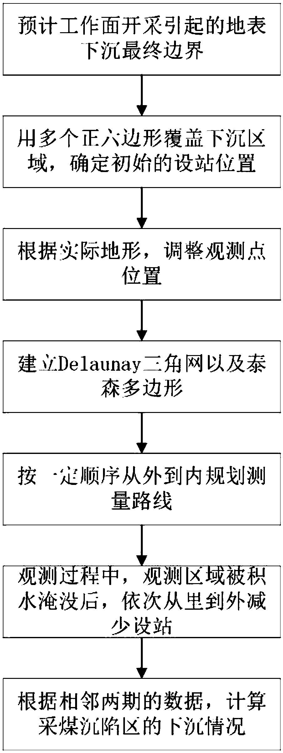
[0029] see Figure 1-7 , the present invention provides a kind of technical scheme: it is characterized in that: described specific steps are as follows:

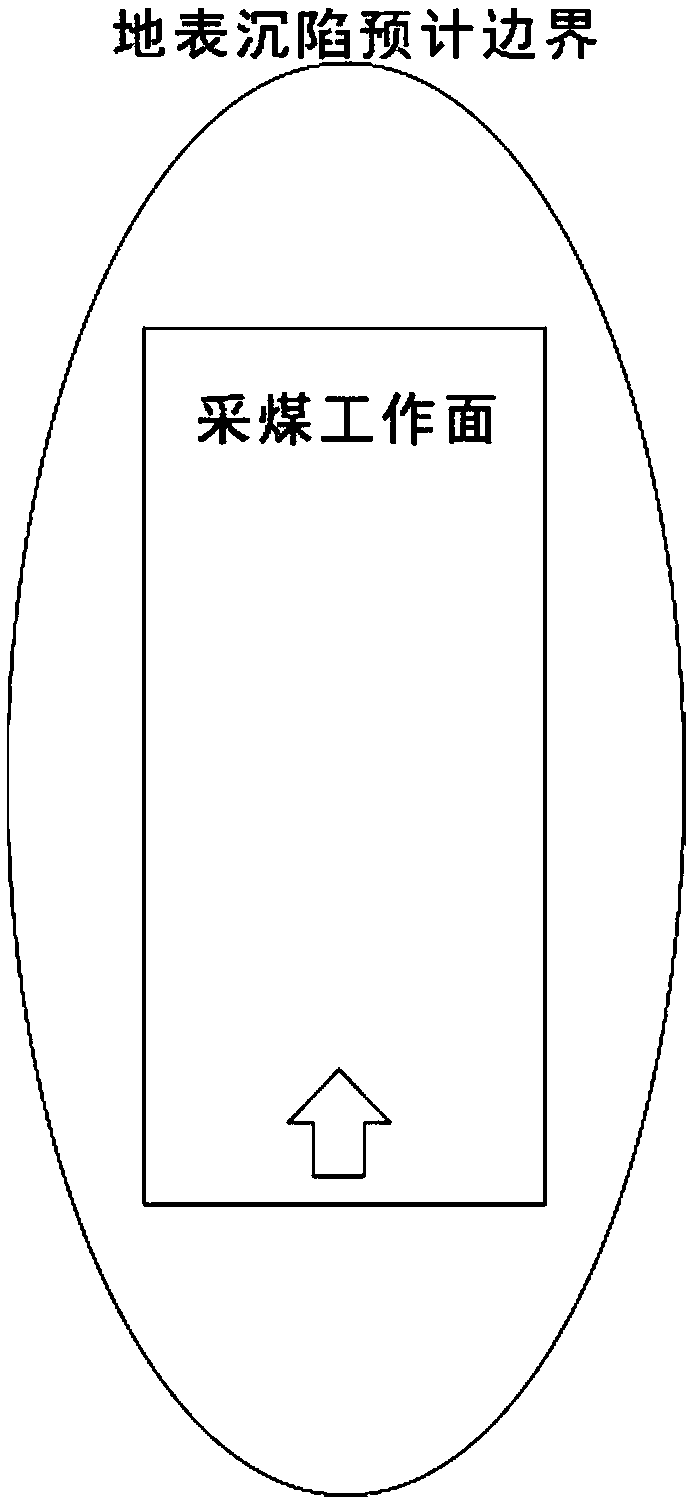
[0030] The first step is to estimate the range of surface subsidence caused by the mining of the working face according to the location, size and geological mining conditions of the coal mining face, and extract the boundary of the subsidence basin;

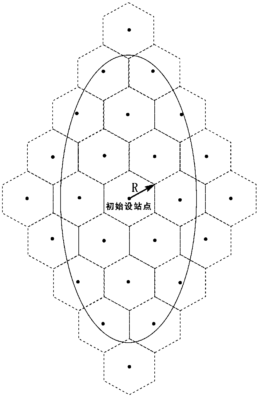
[0031] In the second step, the optimal scan radius is first ...


PUM


Abstract

The invention discloses a laying method for the ground surface settlement monitoring point on the basis of three-dimensional laser scanning, and belongs to the technical field of ground surface settlement monitoring. The characteristics of a polygon sampling point on any position in a Thiessen polygon is used for effectively dividing a mining area subsidence area into a plurality of Thiessen polygons; then, a ground surface settlement monitoring point is laid on the Thiessen polygon sampling point, and a monitoring route is planned according to a certain sequence from an outermost layer to inside; according to the planned route, a three-dimensional laser scanner is erected on the monitoring point; the point cloud data of the subsidence area is obtained in fixed time; and after ground surface settlement is stable, the ground surface settlement situation of the subsidence area is calculated. By use of the method, the subsidence area is effectively divided into a plurality of Thiessen polygons to guarantee that three-dimensional laser scanning data is evenly distributed, a blind area is avoided, the mining area ground surface extraction speed of three-dimensional laser scanning is effectively improved, later-stage point cloud data processing efficiency is improved, later-stage processing errors are reduced, and meanwhile, the problem of monitoring point laying after the subsidencearea is subjected to ponding along with coal layer mining is avoided.

Description

technical field [0001] The invention relates to the technical field of monitoring methods for surface subsidence in mining areas, in particular to a method for setting up stations for monitoring surface subsidence in mining areas by three-dimensional laser scanning. Background technique [0002] Underground mining in the mining area will cause the overlying rock to break, move, and surface subsidence, resulting in damage to buildings in the surface subsidence area. Therefore, it is necessary to carry out effective subsidence monitoring on the surface subsidence area of ​​the mining area, so as to formulate corresponding measures to reduce the impact of surface subsidence on the surface. destruction of buildings. The traditional mining area surface subsidence monitoring method mainly arranges a certain density of monitoring points on the direction and dip main section of the subsidence basin, and then uses level instruments, theodolites, total stations and other instruments t...

Claims


Application Information

Patent Timeline
Patent Type & Authority Applications(China)
IPC IPC(8): G01C5/00
CPCG01C5/00
Inventor 朱晓峻刘辉陈晓谢
Owner ANHUI UNIVERSITY
Why Eureka
Try Eureka