
Electro-optic modulation method, electro-optic modulation equipment and application and regenerative amplifier thereof

A regenerative amplifier, electro-optic modulation technology, used in instruments, optics, nonlinear optics, etc., can solve the problem of high voltage

Pending Publication Date: 2019-01-22
LAIZE PHOTONICS CO LTD
View PDF8 Cites 2 Cited by
  • Summary
  • Abstract
  • Description
  • Claims
  • Application Information

AI Technical Summary

Problems solved by technology

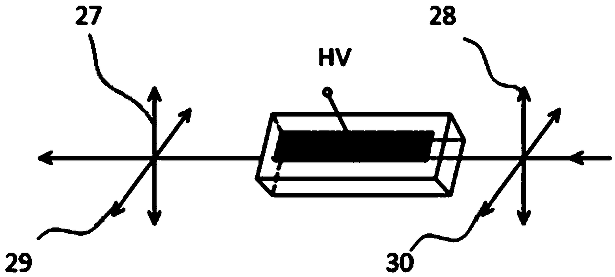
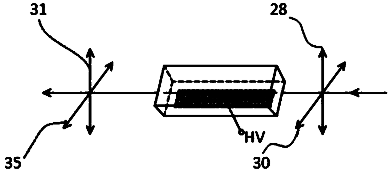
[0007] In order to overcome the problem that the modulation voltage of the existing electro-optical switch is too high, an electro-optic modulation method, an electro-optic modulation device and its application, and a regenerative amplifier that can reduce the operating voltage and are simple to operate are provided

Method used


Image

  • Electro-optic modulation method, electro-optic modulation equipment and application and regenerative amplifier thereof
  • Electro-optic modulation method, electro-optic modulation equipment and application and regenerative amplifier thereof
  • Electro-optic modulation method, electro-optic modulation equipment and application and regenerative amplifier thereof

Examples


Embodiment Construction

[0034] In order to make the purpose, technical solution and advantages of the present invention clearer, the present invention will be further described in detail below in conjunction with the accompanying drawings and embodiments. It should be understood that the specific embodiments described here are only used to explain the present invention, not to limit the present invention.

[0035] An electro-optic modulation method in an embodiment includes the following steps:

[0036] S10. Emitting laser light through the glass slide and the electro-optic crystal in sequence, the electro-optic crystal including a first surface and a second surface oppositely arranged.

[0037] Wherein, the slide can be a quarter slide, an eighth slide or a sixteenth slide. It can be understood that the slides are not limited to the above three slides.

[0038] The electro-optic crystal can be BBO crystal, KTP crystal or RTP crystal.

[0039] S20. Apply forward pressure to the first surface of th...


PUM

PropertyMeasurementUnit
refractive indexaaaaaaaaaa

Abstract

The invention discloses an electro-optic modulation method. The method comprises the following steps: emitting laser to pass a slide and an electro-optic crystal in order, wherein the electro-optic crystal comprises a first surface and a second surface opposite to each other; performing forward pressurizing on a first surface of the electro-optic crystal, and performing reverse pressurizing on a second surface of the electro-optic crystal, wherein two steps of performing forward pressurizing on the first surface and performing reverse pressurizing on the second surface are alternatively performed. Through the above electro-optic modulation method disclosed by the invention, the positive pressurizing and reverse pressurizing are alternatively performed on two opposite surfaces of the electro-optic crystal, and rotation directions of polarization states of the laser passing the electro-optic crystal are alternatively changed, thereby changing the laser output direction. A high pressure value loaded on the electro-optic crystal can be effectively reduced, or under the same high pressure and crystal length, greater crystal light passing aperture can be allowed, thereby reducing the manufacturing difficulty of the electro-optic switch driving device. Furthermore, the invention further provides electro-optic modulation equipment and application thereof, and a regenerative amplifier.

Description

technical field [0001] The invention relates to the technical field of laser devices, in particular to an electro-optic modulation method, an electro-optic modulation device and its application, and a regenerative amplifier. Background technique [0002] In pulsed lasers, due to the fast response speed of electro-optic modulation, pulses with a narrow time width can be generated, and as switches and selection devices, high repetition frequency pulse selection can be performed, so electro-optic modulation is used in Q-switched lasers, regenerative amplifiers, and cavities It is widely used in external switch control. However, because electro-optic crystals require a very high quarter-wavelength or half-wavelength modulation voltage, especially for laterally pressurized Pockels cells, the high voltage value is proportional to the distance between the two pressurized surfaces and proportional to the crystal length. inverse ratio. However, it is very difficult for existing dri...

Claims


Application Information

Patent Timeline
Patent Type & Authority Applications(China)
IPC IPC(8): G02F1/03G02F1/07G02F1/01
CPCG02F1/0136G02F1/0311G02F1/0327G02F1/076G02F1/0142
Inventor 艾庆康舒严
Owner LAIZE PHOTONICS CO LTD
Learn More